


23
Range and inteRfeRence testing
The frequency scanning capability of the XD-V75 receiver, plus the A / B antenna metering on the
display and the RF LED ladder, provide powerful tools for selecting the clearest channels, avoiding
interference, and preventing the wireless microphone systems from interfering with other wireless
devices. Using these functions before operating the systems in new locations will ensure trouble-free
and compatible performance.
Scanning the Channels for Interference
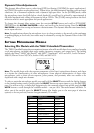
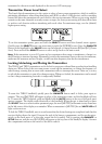
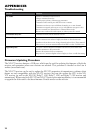
The first step is to scan the channel using the process in Channel Scanning Procedure. Channels
1 – 14 are spread across a 76 MHz band of the 2.4 GHz spectrum, and the frequencies are specially
selected for compatible operation and to minimize interference with other equipment working in the
same spectrum. Perform a scan with all transmitters off at first when in a new location.
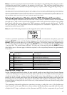
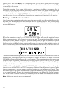
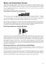
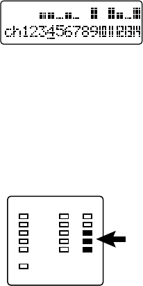
Once the scan is complete, look at the results on the channel display, especially noting any channels
with the half block or full block icon above them. This indicates significant existing interference to
those channels, which will limit the range of transmitters using those channels (and also means that a
transmitter on that channel could interfere with the existing other equipment).
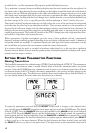
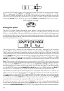
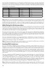
Detecting Interference with the RF Meter
RFBATTERYAUDIO
MUTE
TRANSMITTER
STATUS
The XD-V75 receiver has an LED ladder (stacked LED meter) labeled RF, which detects signals on the
channel frequencies to which it is currently set (for example, when set to Line 6 channel 7, it detects
frequencies with either a 2.433 GHz or 2.467 GHz center frequency). These LED’s are green when
receiving signal from a Line 6 transmitter, and red when the transmitter is off and interfering signals on
that frequency are present. If the receiver is on and the associated transmitter is off, and one or more
of the LEDs on the RF meter are lit red, it is detecting a potentially interfering signal. The more LEDs
that are lit, the stronger the signal – and the more it will interfere with the range and performance of a
transmitter on that channel.
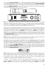
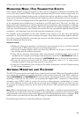
Detecting Interference with the Antenna A & B Display
The main receiver display page shows the received signal strength on antennas A and B for both of
the frequencies emitted from the associated Line 6 transmitter. They can also show the presence of
interfering signals when the transmitter is off.
The four vertical bars (Antenna Bars) that can appear on the left and right sides of the A and B on
the display represent increasing levels of RF signal – with 4 bars being the highest level. With the
transmitter off, the appearance of one or more bars next to those letters shows a potentially interfering
signal on that channel which can affect the performance and range of the wireless system.