


10
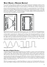
to a digital word of 1’s and 0’s, that information will be ignored. If noise is riding on those digital words,
it is still decoded as one of two states – rather than something in-between, if it were analog. As long as
the digitally modulated carrier arrives at the receiver’s antenna with sufficient level, it will be accurately
decoded. And as with CD players and other digital audio devices, error concealment algorithms may be
added to fill in the gaps where there is missing information.
Typically with a digital wireless system, the signal will retain its quality until the signal level is too low,
and then it’s gone. The main effect that interference has on a digital wireless system is that it will shorten
the maximum range between the transmitter and receiver antenna. To alleviate potential problems,
maintain line-of-sight between transmitter and receiver, locate the receiver / receiver antennas at a
distance from interfering sources such as WiFi routers, and use the HI setting on the transmitter when
operating at longer distances.
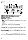
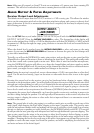
Xd-V75 ReceiVeR detailed setuP
For stand-alone placement, position the receiver on a level surface where the front-panel controls and
displays are visible. Connect the supplied DC-1G power supply to the
9VDC In connector on the rear
panel; to secure, press a loop of the cable through the cable holder located above the connector to
prevent accidental disconnection. Plug the power supply into an available AC outlet that provides
voltage from 90 – 240 VAC.
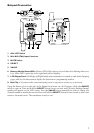
Place the supplied half-wave articulating antennas (RDrac) on to the outer left and right BNC
connectors marked
ANTENNA A and ANTENNA B. Rotate a quarter-turn clockwise, and then
position the antennas at an approximately 45 degree “rabbit ears” orientation. For details on front-
mounting antennas when rack-mounting, or connecting multiple receivers, see Antenna Mounting
and Placement.
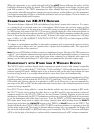
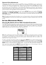
On the right side of the front panel, turn on the power switch; the display will light. Press the
SETUP
button. The two-line display will show [SELECT FUNCTION] in the top position, and turning the
ROTARY ENCODER will scroll through a list of editable functions. Scroll to [SET CHANNEL] and
press the
ROTARY ENCODER to select; pressing the SETUP button also will select the function.
Note, Turn clockwise to scroll down the list, and counterclockwise to return to the top of the list.
CH 1:THH12B
8:00
SET CHANNEL:
14
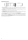
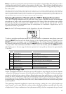
The [SET CHANNEL] edit page will show the currently selected channel. Turn the encoder to change
the channel; any channel number other than the one currently selected will flash. Press the
ROTARY
ENCODER to select the new channel.
Note, The receiver’s RF channel will not actually change to a different frequency until the ROTARY
ENCODER is pressed.
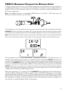
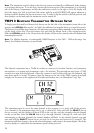
To sync the handheld or beltpack transmitter to the receiver, follow the procedure in the following
transmitter quick setup sections. For more details on scanning channels and using multiple wireless
units together, see Channel Scanning Procedure, Range and Interference Testing, and Minimizing Near / Far
Transmitter Effects.
To adjust the output level of the receiver going to the mixing console or other audio equipment, see
Audio Output and Filter Adjustments.
Note, The receiver provides three display modes. The Main Page shows the currently selected channel,
transmitter name or designation, remaining battery life, and the performance of antennas A and B. The
[SELECT FUNCTION] page has a scrollable list of editable receiver operations. The Edit page allows
changes to be made to the currently selected function. The only user operations available are pressing
SETUP and EXIT, and turning or pressing the ROTARY ENCODER knob.