Understanding Room Equalization
1-2
Lexicon MC-12 Controller
UNDERSTANDING ROOM EQUALIZATION
Sections one and two of this document explain the conditions that
create the need for room equalization, how the MC-12 can com-
pensate for room variances, and how to properly set up the micro-
phones to run equalization tests. The theoretical material in this
section was authored by Dr. James Muller, Lexicon senior software
engineer.
LOUDSPEAKER SOUND IN A ROOM
The way that sound from a speaker behaves outdoors (in open air)
or in an anechoic chamber is different from the way it behaves in
a room. The sound from a speaker in open air or in an anechoic
chamber radiates outward in straight lines. (Actually, the theory of
wave propagation is quite complex, but the “straight line” concept
is valid for uniform air properties and is therefore accurate enough
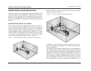
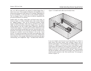
to be useful.) In a typical listening room, a small amount of the
sound reaches the listener directly, as shown in Figure 1-1.
Figure 1-1. The listener directly hears a fraction of the total sound.
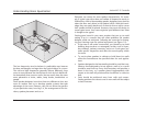
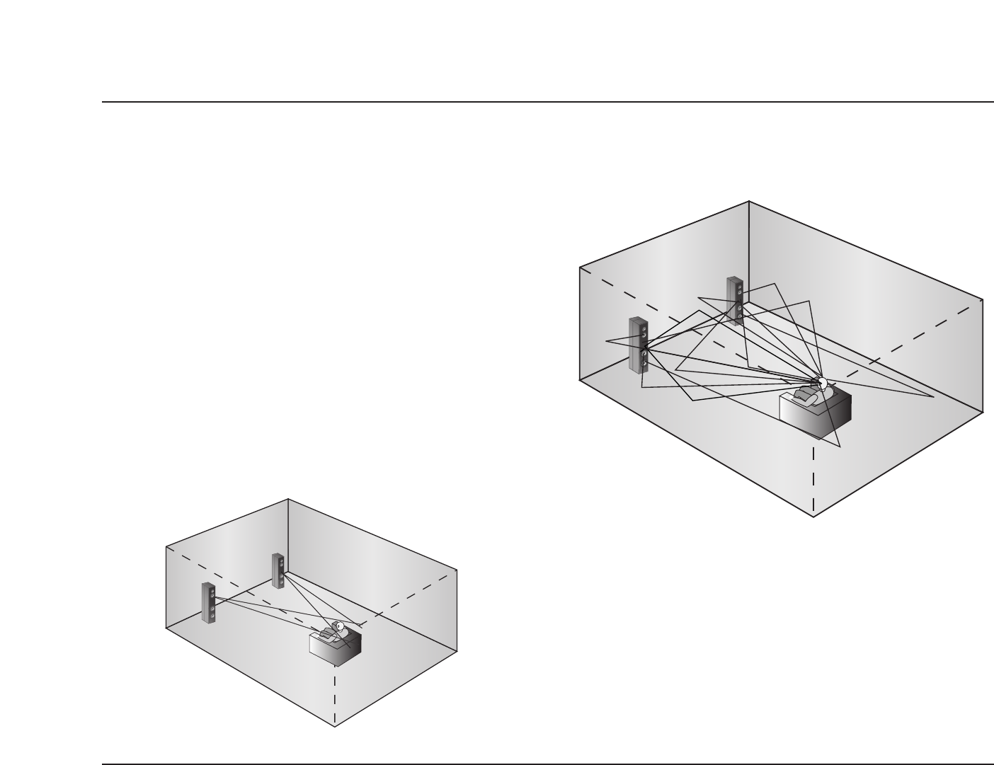
Most of the sound in a room is reflected off walls, the floor and the
ceiling, as shown in Figure 1-2.
In addition, a typical listening room also contains furniture, win-
dows, door openings and people. Every object and surface con-
tributes a reflection.
The strength of each reflection depends on how the wavelength of
the sound compares to the size of the reflecting object, and on the
transmission properties of the reflector. A good general principle to
remember is that if the wavelength is longer than the size of the
object, the wave will pass around the object as if it wasn’t there. If
the wavelength is shorter, strong reflections will occur. For exam-
ple, the wavelength of 100Hz is 11 feet, so it will pass around any
person standing in a room. The wavelength of 1000Hz is only 1.1
Figure 1-2. The listener hears mostly reflected sound.


