


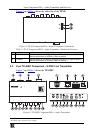
Your Component/XGA – Audio Transmitter and Receiver
7
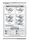
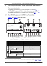
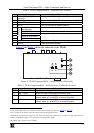
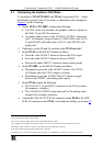
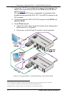
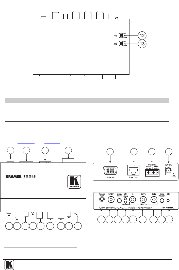
Figure 2 and Table 2 define the underside of the TP-45:
Figure 2: TP-45 Component/XGA – Audio Transmitter (Underside)
Table 2: TP-45 Component/XGA – Audio Transmitter (Underside) Features
# Feature Function
12 VS Switch Slide the switch up
1
(to NEG.) to change the VS polarity to negative polarity;
slide the switch down (to NORM) to retain the polarity
13 HS
Switch Slide the switch up
1
(to NEG.) to change the HS polarity to negative polarity;
slide the switch down (to NORM) to retain the polarity
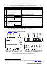
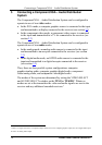
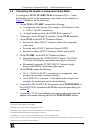
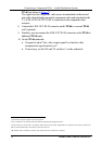
4.2 Your TP-45RC Component – S/PDIF Line Transmitter
Figure 3
and Table 3 define the TP-45RC:
Figure 3: TP-45RC Component/XGA – Audio Transmitter
1 By default, both switches are set to NORM
10
10
7
7
11
11
12
12
8
8
13
13
9
9
1
1
2 3
2
4
34
5
5
6
6