


Connecting a Component/XGA – Audio Distribution System
17
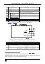
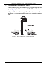
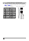
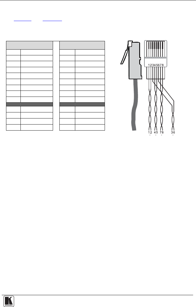
5.4 Wiring the Twisted Pair LINE IN / LINE OUT RJ-45 Connectors
Table 6
and Figure 9 define the twisted pair pinout, using a straight pin-to-pin
cable with RJ-45 connectors:
Table 6: Twisted Pair PINOUT
Figure 9: Twisted Pair PINOUT
EIA /TIA 568A EIA /TIA 568B
PIN Wire Color PIN Wire Color
1 Green / White 1 Orange / White
2 Green 2 Orange
3 Orange / White 3 Green / White
4 Blue 4 Blue
5 Blue / White 5 Blue / White
6 Orange 6 Green
7 Brown / White 7 Brown / White
8 Brown 8 Brown
Pair 1 4 and 5 Pair 1 4 and 5
Pair 2 3 and 6 Pair 2 1 and 2
Pair 3 1 and 2 Pair 3 3 and 6
Pair 4 7 and 8 Pair 4 7 and 8