


Your Component/XGA – Audio Transmitter and Receiver
9
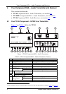
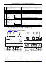
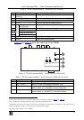
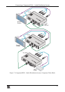
Table 4: TP-46 Component/XGA – Audio Receiver Features
# Feature Function
1 XGA OUT 15-pin HD (F)
Connector
Connect to the XGA acceptor
2 LINE IN RJ-45 Connector Connect to the LINE OUT RJ-45 connector on the TP-45
1
3 LINE OUT RJ-45 Connector Connect to the LINE IN connector on an additional TP-46
1
4
12V DC
+12V DC connector for powering the unit
5
OUTPUTS
ANALOG AUDIO 3.5mm
Mini Connector
Connect to the stereo analog audio acceptor
6 S/PDIF RCA Connector Connect to the digital audio acceptor
7 Y RCA Connector Connect to the component video acceptor
8 CB/PB RCA Connector
9 CR/PR RCA Connector
10 LINK LED Lights when receiving the correct input signal
11 ON LED Lights when receiving power
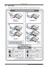
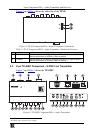
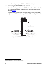
Figure 5 and Table 5 define the underside of the TP-46:
Figure 5: TP-46 Component/XGA – Audio Receiver (Underside)
Table 5: TP-46 Component/XGA – Audio Receiver (Underside) Features
# Feature Function
12 LEVEL Trimmer Adjusts
2
the output signal level
13 EQ.
3
Trimmer Adjusts
1
the cable compensation equalization level
14 VS Switch Slide the switch down (to NORM) to retain the polarity
Slide the switch up
4
(to INVERT) to invert the VS polarity
15 HS Switch Slide the switch down (to NORM) to retain the polarity
Slide the switch up
1
(to INVERT) to invert the HS polarity
1 Using a UTP cable with CAT 5 connectors at both ends (the PINOUT is defined in Table 6 and Figure 9)
2 Use a screwdriver to carefully rotate the trimmer, adjusting the appropriate level
3 Degradation and VGA/XGA signal loss can result from using long cables (due to the effects of stray capacitance, for
example), sometimes leading to a loss of sharpness in high-resolution signals
4 By default, both switches are set to NORM