


SummitView™ System Cables
33
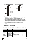
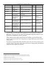
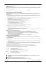
Table 9: Terminal block Connector Pinout (England and Europe)
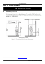
SV-301, SV-304, SV-305 Rear Panel PINOUT
SV-302, SV-303 Rear Panel PINOUT
Brown
Brown
Gnd
Brown / White
Brown / White
Green
Green
Blue / White
Blue / White
Blue
Blue
Green / White
Green / White
Orange
Orange
Orange / White
Orange / White
DDC
PC
Brown
Gnd
Brown / White
Green
Blue / White
Blue
Green / White
Orange
Orange / White
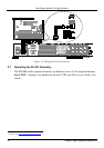
Video
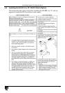
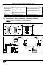
Notes:
• The “PC” section has 9 pins; the “DDC” section has 8 pins. Only use the
connector clips to remove the wires, not when inserting them
• Each wire protrudes 9mm in length from the plastic casing so that it can
be easily connected. To prevent the wires crossing, be sure that each wire
is completely inserted
• With STP cable, the GND pin is used for shielding. For the DDC
channel, shielding is not needed, but if desired, connect the GND pin of
the PC
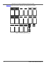
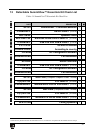
9 SummitView™ System Cables
Table 10 defines the recommended cables for a SummitView™ installation.
Table 10: Cables included with the SV-551 SummitView™ Essentials Kit and SV-551 ALC
Cable Name Description Function SV-551
ALC
Essentials Kit
Power Cord AC mains cable Connect the SV-551 to the AC
mains supply
1 1
C-MGM/MGM-3 Molded Micro VGA to
VGA cable 3ft (0.91m)
Connect the SV-551 to a display
device
1 1
C-RVM/RVM-3 Molded RCA RG-59
video cable 3ft (0.91m)
Connect the SV-551 to a display
device
1 1
C-SM/SM-3 s-Video cable 3ft
(0.91m)
Connect the SV-551 to a display
device
1 -
C-R3VM/R3VM-3 Component MINI high
resolution cable 3ft
(0.91m)
Connect the SV-551 to a display
device
1 -