


Defining the SV-551 SummitView™ Processor/Switcher
11
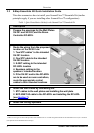
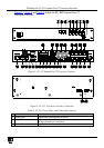
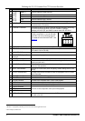
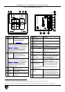
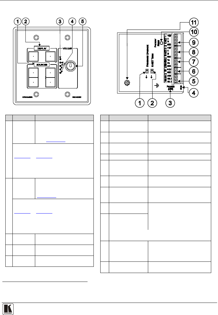
Table 3: Defining the RC-63DL
1
#
Feature
Function
1 SOURCE
Buttons
These 4 configurable backlit
buttons can set up any
supported command
(see Section 8.1
)
"SOURCES" is printed on the panel, or it
is left blank to affix your own label (see
Figure 17 in Section 7), or an LCD version
on a blue background is available that
displays up to 8 characters at once
(programmed via the USB port) and
includes rolling text
2 DISPLAY
Buttons
These 2 configurable backlit
buttons can set up any
supported command (see
Section
7.1)
" DISPLAY " is printed on the panel, or it is
left blank to affix your own label (see
Figure 17 in Section 7), or an LCD version
on a blue background is available that
displays up to 8 characters at once
(programmed via the USB port) and
includes rolling text
3 VOLUME
LED
Lights red, indicating
maximum volume
4 VOLUME
LEDs
Lights green, indicating
volume level
5 VOLUME
Knob
Rotate clockwise to increase
the level
#
Feature
Function
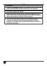
1 FIRMWARE
UPGRADE Switch
For technical support use only
2 K-NET TERM
Switch
For line termination
3 PROGRAM (USB)
Connector
Connect to a computer for unit
configuration
4 IR IN Receiver Receives IR remote commands
5 RELAY Connections Connect to room items (such as
lighting, screen settings, blinds,
and so on)
6 IR Connections Control a machine via an IR
Emitter
7 RS-232
Connections
Connect to the RS-232 connector
on the A/V equipment or a PC or
other Serial Controller
8 K-NET 2
Connections
On K-NET 1 and K-NET 2, PIN
GND is for the Ground
connection
2
9
; PIN B (-) and PIN
A (+) are for RS-485, and PIN
+12V is for powering the unit
K-NET 1
Connections
(K-Net is a proprietary protocol for interconnecting
Kramer units)
10 FACTORY RESET
Button
Press and hold while powering
up the unit to reset the audio,
switching and Ethernet settings
to their factory default values
11 Grounding Screw Connects to the grounding wire
1 US version is shown. For the European version, see the RC-62, RC-63A and RC-63D Series user manual
2 The ground connection is sometimes connected to the shield of the RS-485 cable (in most applications, it is not connected)