


KRAMER: SIMPLE CREATIVE TECHNOLOGY
Defining the SV-551 SummitView™ Processor/Switcher
16
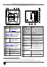
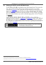
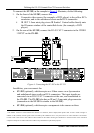
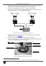
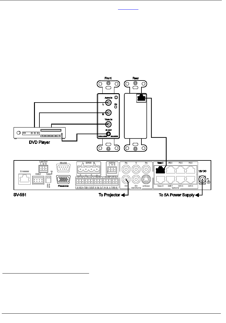
To connect the SV-302, as the example in Figure 4 illustrates, do the following:
1. On the front of the SV-302, connect the:
Composite video source (for example, a DVD player) to the yellow RCA
connector, and to the unbalanced stereo audio RCA connectors
IR OUT 3.5mm mini plug via an IR Emitter
1
2. On the rear of the SV-302, connect the RJ-45 CAT 5 connector to the VIDEO
1 INPUT on the SV-551.
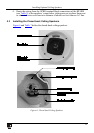
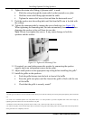
Control cable directly onto
the IR sensor window of the controlled device (for example, a DVD
player)
Figure 4: Connecting the SV-302 to the SV-551
In addition, you can connect the:
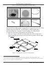
• SV-303 (optional), which accepts an s-Video source on a 4p connector
and unbalanced stereo audio on RCA connectors. The input signals are
converted via an RJ-45 CAT 5 connector at the rear, and transmitted to
the SV-551. The SV-303 also has an IR out 3.5mm mini plug connector
(connection to the SV-551 is similar to the SV-302)
• SV-304 (optional), which accepts a component video source on three
1 The Emitter contains a small infrared LED housed in a miniature, mouse shaped, black plastic shell. It emits visible red light in
addition to IR (infrared) control signals when activated by IR commands sent to it by IR receivers or other controllers. The Emitter
Control Cable comes with a clear adhesive film included on the emitter housing for attachment to the IR window of the controlled
component and pieces of double-sided clear adhesive tape included for replacement purposes