2
XL-MC334BK
LVT0022-001B [J]
PRECAUTIONS SETTING UP
Installation
• Select the best location
Select a level location to install this unit, where it is free from
extremes of temperature (5 to 35°C, or 41 to 95°F) and humidity,
dust, or vibration.
If noise interference is caused when receiving AM broadcast by
a tuner/receiver located nearby, relocate it or this unit, or turn off
either one.
• Moving the unit
Before moving the unit, first remove all discs. Turn the power
off, making sure the standby indicator is on. Then remove the
AC power cord from the AC outlet.
Compact discs
• Use only compact digital audio discs
Only audio compact discs identified by the
logo on the right can be played back with the
unit.
Also the unit can display the text information
in CD text discs identified by the logo on the
right.
Operation
• Place only discs in the disc storage
Do not put anything other than discs in slots of the disc storage.
• Turn the power off if a problem occurs
If an unusual condition arises, turn the power off immediately. If
the condition persists whenever the power is turned on, consult
your JVC dealer.
• Do not pull the AC cord
Do not pull the cable when unplugging the AC cord from the AC
outlet or this component — hold and pull the plug body.
• Set the sound volume carefully
Be careful in setting the sound volume on your amplifier/receiver
when playing a CD, which has almost no background noise unlike
analog records and tapes. Find the right setting by starting with a
low level setting. Setting the level too high and then playing a
CD could damage the speakers.
• Protect the unit against condensation
Condensation on the unit could disrupt the proper transmission
of the disc-reading laser beam, causing noise or malfunction. If
condensation occurs due to excessive humidity or sudden
temperature change, leave the unit turned on for a couple of hours
to dry — consult your JVC dealer if this does not correct the
condition.
Connecting the unit
This compact disc changer/player needs to be connected to an
amplifier/receiver for audio reproduction.
CAUTION
Do not connect the AC power cord until all other neces-
sary connections have been made.
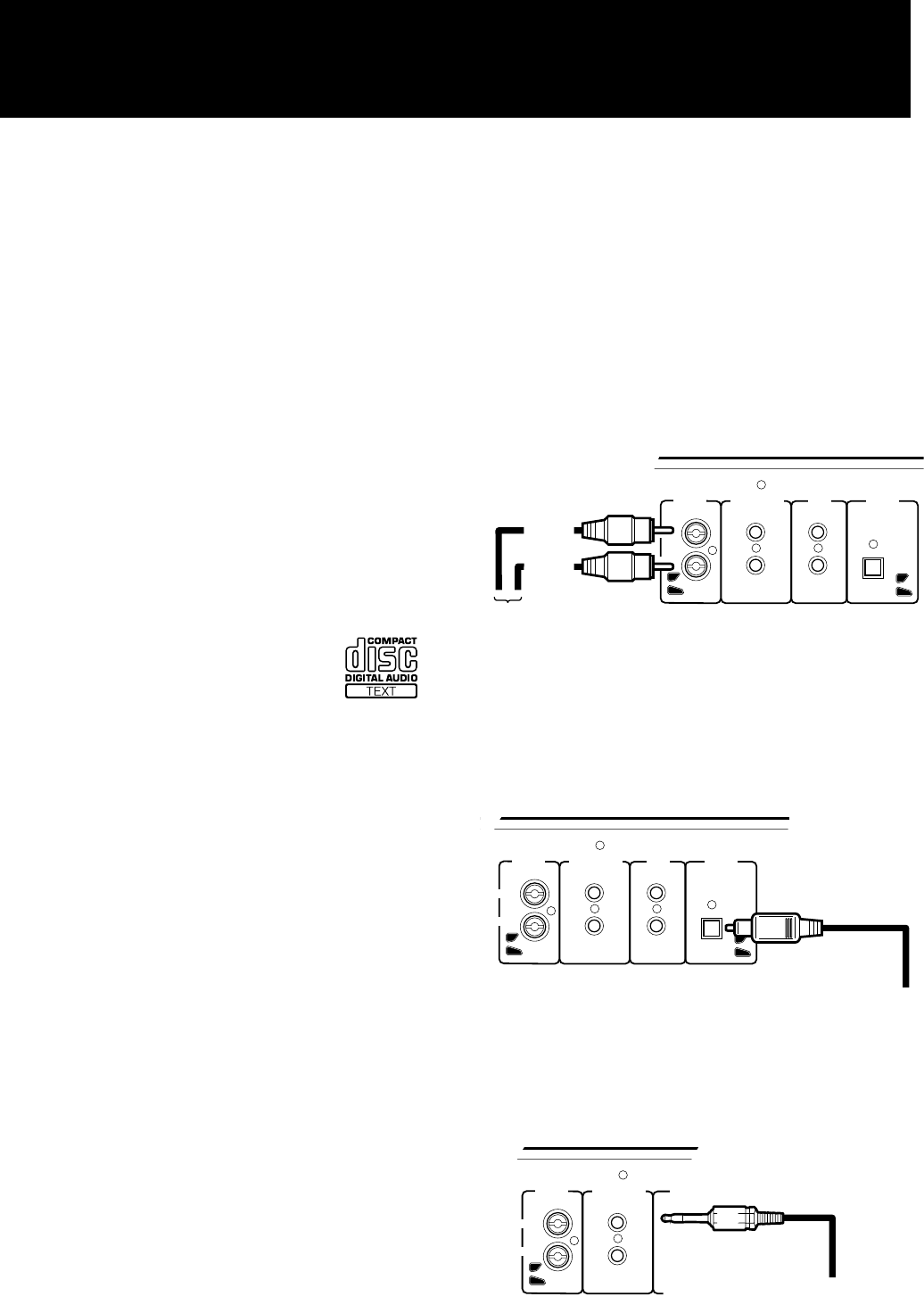
1. Audio connection
Connect the analog (OUTPUT) ports on the back of this unit
with the CD or AUX input ports of the amplifier/receiver using
the supplied audio cords (red and white).
OUTPUT COMPULINK-3
(SYNCHRO)
RIGHT
LEFT
TEXT
COMPULINK
DIGITAL
(OPTICAL)
(Red)
(White)
To input audio jack of
the amplifier/receiver
Audio cord
• Be sure to insert the plug firmly into the proper ports.
• Be sure to match the output and input channels—RIGHT to
RIGHT and LEFT to LEFT.
If your audio unit has a digital optical input, you may connect
the DIGITAL (OPTICAL) port on the back of this unit to it
using the optional digital cord.
OUTPUT COMPULINK-3
(SYNCHRO)
RIGHT
LEFT
TEXT
COMPULINK
DIGITAL
(OPTICAL)
To Digital jack
Digital cord
2. COMPU LINK-3 connection
If you are using a JVC audio amplifier/receiver supporting the
COMPU LINK-3 remote control system, connect either one of
the COMPU LINK-3 (SYNCHRO) ports on the back of the
unit with the amplifier/receiver’s COMPU LINK-3 port using
the supplied compulink cord (black).
OUTPUT COMPULINK-3
(SYNCHRO)
RIGHT
LEFT
TEXT
COMPULINK
DIGITAL
(OPTICAL)
To COMPU LINK jack
COMPU LINK cord
(Black)
By using the COMPU LINK-3 system, you can control the unit
from the connected JVC amplifier/receiver.
(See “COMPU LINK-3 REMOTE CONTROL SYSTEM” on
page 21.)
'


