


5
Getting Started
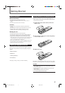
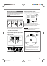
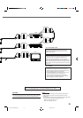
Connecting the FM and AM Antennas
AM loop antenna
(supplied)
If AM reception is poor,
connect an outdoor single
vinyl-covered wire (not
supplied).
FM antenna (supplied)
If FM reception is poor, connect
outdoor FM antenna (not supplied).
Snap the tabs on the loop into
the slots of the base to
assemble the AM loop antenna.
AM LOOP
FM 75
COAXIAL
AM EXT
SUB-
WOOFER
OUT
DIGITAL 1
(STB)
DIGITAL 2
(TV)
PCM/STREAM
FRONT
SPEAKERS
REAR
SPEAKERS
CENTER
SPEAKER
DIGITAL IN
ANTENNA
TAPE / CDR
AUDIO
AV IN/OUT
CAUTION:
SPEAKER
IMPEDANCE
816
AV COMPU LINK-
RIGHT
LEFT
IN
(PLAY)
OUT
(REC)
DIGITAL OUT
RGB YC
STB
TV
VCR
AV IN
RIGHT RIGHT LEFTLEFT
FM 75
COAXIAL
ANTENNA
AM LOOP
FM 75
COAXIAL
AM
EXT
B
FM 75
COAXIAL
1
23
1
2
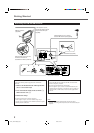
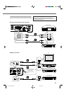
Rear panel of the unit
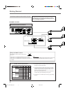
AM antenna connection
Connect the AM loop antenna supplied to the AM LOOP
terminals.
1
Remove the insulation if the AM loop antenna
wire is covered with vinyl.
2
Press and hold the clamp of the terminal (1),
then insert the wire (2).
3
Release the clamp.
Turn the loop until you have the best reception.
• If the reception is poor, connect an outdoor single vinyl-
covered wire (not supplied) to the AM EXT terminal. Keep the
AM loop antenna connected.
FM antenna connection
Connect the FM antenna supplied to the FM 75 Ω COAXIAL
terminal as temporary measure.
Extend the supplied FM antenna horizontally.
• If the reception is poor, connect an outdoor FM antenna (not
supplied). Before attaching a 75 Ω antenna with a coaxial type
connector (IEC or DIN 45325), disconnect the supplied FM
antenna.
Note:
• Make sure the antenna conductors do not touch any other
terminals, connecting cords and power cord. This could cause poor
reception.
EN01_10RX-DV5SL[B]2.pm5 02.8.6, 6:01 PM5