


9
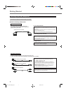
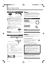
Turn off all the components and the unit before connection.
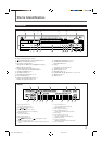
Illustrations of the input/output terminals below are typical
examples. When you connect other components, refer also to
their manuals since the terminal names actually printed on the
rear vary among the components.
Getting Started
DO NOT connect a TV through a VCR or a TV with a built-in
VCR; otherwise, the picture may be distorted.
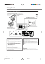
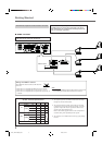
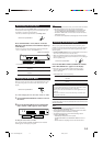
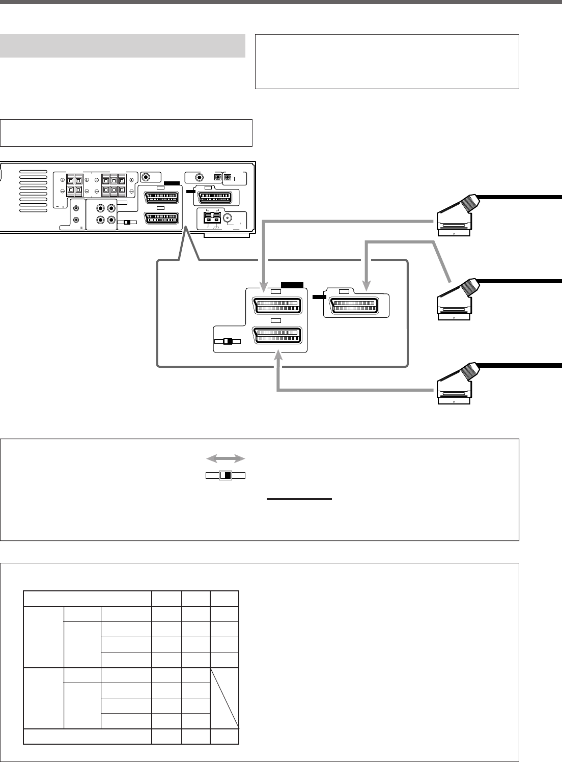
■ SCART connection
*1 The signals input from a SCART terminal cannot be output
through the same SCART terminal.
*2 The video format of the output video signals are consistent
with that of the input video signals. For example, if S-video
signals are input to this unit, no signals other than S-video
signals can be output from this unit.
Refer to the manuals supplied with the video components to
check the setting of the input/output video signals.
*3 The signals for T-V LINK function are always going through
the unit.
SCART Terminal Specifications
TV VCR STB
AUDIO L/R ⅜⅜⅜
IN
Composite
⅜⅜⅜
VIDEO S-video − ⅜⅜
RGB − ⅜⅜
AUDIO L/R ⅜*1 ⅜*1
OUT
Composite
⅜*1*2 ⅜*1*2
VIDEO S-video ⅜*2 −
RGB ⅜*2 −
T-V LINK ⅜*3 ⅜*3 ⅜*3
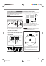
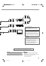
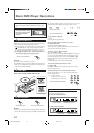
Setting the RGB/YC selector
Set the RGB/YC selector as follows while the unit is
turned off:
• When the TV is compatible with RGB signal, set to “RGB.”
• When the TV is compatible with S-video signal, set to “YC.”
• When the TV is compatible with composite video signal only, set
to “RGB.”
Note:
• If you change the RGB/YC selector setting while the unit is turned
on, this setting will not take effect until the unit is turned off.
RGB YC
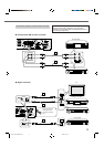
AM LOOP
FM 75
COAXIAL
AM EXT
SUB-
WOOFER
OUT
DIGITAL 1
(STB)
DIGITAL 2
(TV)
PCM/STREAM
FRONT
SPEAKERS
REAR
SPEAKERS
CENTER
SPEAKER
DIGITAL IN
ANTENNA
TAPE / CDR
AUDIO
AV IN/OUT
CAUTION:
SPEAKER
IMPEDANCE
816
AV COMPU LINK-
RIGHT
LEFT
IN
(PLAY)
OUT
(REC)
DIGITAL OUT
RGB YC
STB
TV
VCR
AV IN
RIGHT LEFTRIGHT LEFT
RGB
AV IN/OUT
YC
STB
TV
VCR
AV IN
RGB/YC selector
EN01_10RX-DV5SL[B]2.pm5 02.8.6, 6:01 PM9