


10
Y P
B
P
R
DVR/DVD
IN
MONITOR
OUT
L
R
D
EO
N
MONITOR
OUT
O
OUT
SUBWOOFER
Åı
Y P
B
P
R
VIDEO
S-VIDEO
COMPONENT
DVR/DVD
IN
MONITOR
OUT
VIDEO
IN
VIDEO
VIDEODVR/DVD
ININ
MONIT
OUT
AUDIO
Y P
B
P
R
ıÇÎ
Å
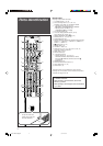
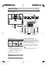
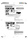
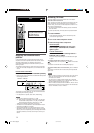
Stereo audio cable (not supplied)
Green
Blue
Red
Component video cable (not supplied)
S-video cable (not supplied)
Composite video cable (not supplied)
VCR, etc.
Å To left/right audio channel output
ı To composite video output
Ç To S-video output
Î To component video output
NOTES
• Connect Y, PB, and PR correctly.
• The signals input from S-VIDEO and VIDEO (composite video)
of VIDEO IN jacks are output through SCART terminal (see
page 7).
• S-video signals and composite video signals can be converted
into each other. For details, see page 25.
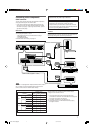
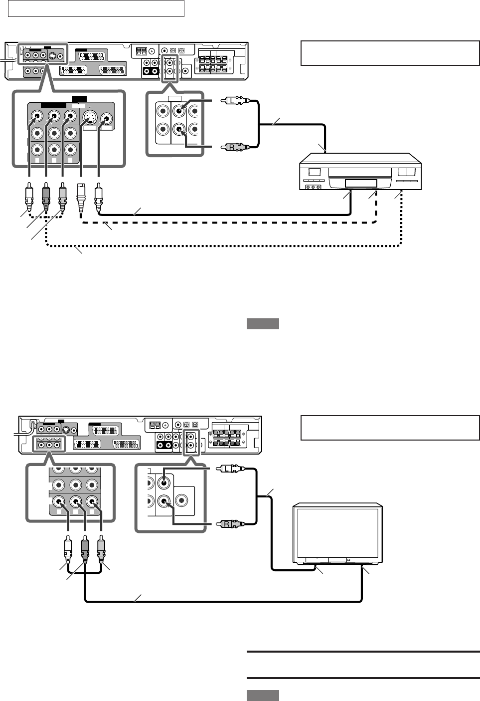
7 Connecting another video component to the VIDEO IN jacks
If your video components have S-video (Y/C-separation) and/or component video (Y, PB, PR) terminals, connect them using an S-video
cable (not supplied) and/or component video cable (not supplied). By using these jacks, you can get better picture quality in the order:
Component video > S-video > Composite video
To enjoy the playback from the component connected to these jacks, select “VIDEO” as the source (see page 12).
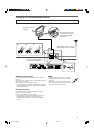
Turn off all components before making
connections.
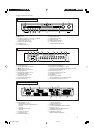
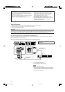
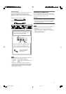
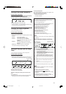
7 Connecting a TV to the MONITOR OUT jacks
Stereo audio cable
(not supplied)
Green
Blue
Red
Component video cable
(not supplied)
TV
Å To left/right audio channel input
ı To component video input
IMPORTANT:
Audio signals come out through the AUDIO MONITOR OUT (RIGHT/
LEFT) jacks ONLY when TV Direct is in use (see page 14).
NOTES
• Connect Y, PB, and PR correctly.
• When connecting a TV through the VIDEO MONITOR OUT
jacks, the on-screen display does not appear on the TV screen
(see page 25).
Turn off all components before making
connections.
White
Red
Yellow
White
Red
EN06-11RXF31S[B]f.p65 05.4.14, 20:0110