


43
Specifications
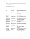
Additional Controls via LSR4300
Control Center Software:
DIM (-12 dB at full volume), System MUTE, Preset
STORE; LOAD Configuration, SAVE Configuration; Level
TRIM +3 dB to – 10 db in ¼ dB increments
Display/
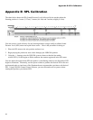
Front Panel Display: 31 LED Segments for dBFS and indication of settings
Front Panel Meter: -70 dBFS to 0 dBFS plus CLIP
Rear Panel Indicators: 5 LED indicate Speaker ID Selection
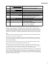
Physical
Finish: Dark graphite
Handles: 2 each, flush mounted on sides
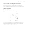
Mounting: 4 threaded mounting points conforming to industry
standard square pattern, 107.9 mm x 50.8 mm (4 ¼” x 2”
in) center to center. M6 metric threads
Low Frequency Vent: Rear ported linear dynamics aperture
Baffle Construction: Injection-molded structural ABS
Enclosure Construction: 19 mm (3/4 in) MDF
Net Weight: 15 kg (32.5 lbs) (LSR4328P)
13 kg (28.5 lbs) (LSR4326P)
Dimensions (WxHxD): 267 mm x 438 mm x 269 mm
(10.5” x 17.25”D x 10.6”) (LSR4328P)
236 mm x 387 mm x 262 mm
(9.3” x 15.25” x 10.3”) (LSR4326P)
Caution: Unsafe mounting or overhead suspension of any heavy load can result in serious
injury and equipment damage. Mounting of speakers should be done by qualified persons in
accordance with all applicable local safety and construction standards. Be certain to follow the
instructions provided by the manufacturer of the mounting bracket. Before selecting a mount-
ing bracket, be certain that it is capable of supporting the weight of the speaker to be mounted.
Notes:
All measurements unless otherwise stated made anechoically in a 4p environment at 2 meters,
referenced to 1 meter by inverse square law.
The reference measurement microphone position is located perpendicular to the centerline of
the low and high frequency transducers at the point 63.5 mm (2.5 in) below the center of the
high frequency diaphragm.
Acoustic loading provided by the listening room increases maximum SPL capability and low
frequency bass extension as compared to stated anechoic values.
Distortion measurements performed with the input voltage necessary to produce the stated
A- weighted SPL at the stated measurement distance. Distortion figures refer to the maximum
distortion measured in any 1/10th octave wide band in the stated frequency range.
JBL continually engages in research related to performance improvements. New materials, pro-
duction methods, and design refinements are introduced into existing products without notice as
a routine expression of that philosophy. For this reason, any current JBL product may differ in
some respect from its published description, but will always equal or exceed the original design
specification unless otherwise stated.