


17
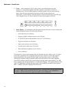
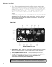
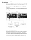
4. RMC Microphone Input – 1/8″ connector for the supplied RMC calibration
microphone. CAUTION: This input connector provides +15 volts of phantom power,
so be sure to not connect any device other than the supplied RMC calibration
microphone to this connector.
5. S/PDIF input connector (phono) – Input connector for incoming digital signal in
two-channel S/PDIF Format
6. S/PDIF output connector (phono) – Output connector used to route incoming S/PDIF
signal to another speaker.
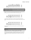
7. AES/EBU input connector (XLR) – Input connector for incoming digital signal in
two-channel AES/EBU Format
8. AES/EBU output connector (XLR) – Output connector used to route incoming
AES/EBU signal to another speaker.
9. Harman HiQnet connectors (RJ45 x 2) – Used to interconnect LSR4300 speakers
together for centralized system control from any speaker or the provided wireless remote
control or LSR4300 Control Center Software.
10. USB connector – Universal Serial Bus Type I connector for computer connection when
using the provided LSR4300 Control Center software.
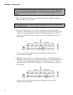
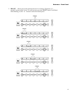
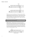
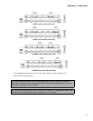
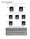
11. DIP switches – These eight switches are used to identify the channel being carried by
each speaker in a networked system. If one of the two digital inputs is being
monitored, the DIP switch setting also determines whether the speaker is reproducing the
left (Channel A) or right (Channel B) side of the incoming stereo signal. In normal
operation, only one DIP switch should be in the up (“on”) position for each speaker. For
more information, see page 21 in this manual.
DIP switches are also used to restore factory settings. See page 30 in this
manual for more information.
12. ACTIVE INPUT display – Whenever the monitor is powered on, one of these LEDs will
be lit, indicating whether the speaker is reproducing signal arriving at the analog input,
or one of the two digital inputs (S/DIF and AES/EBU). If one of the two digital inputs is
being used, the display also shows whether the speaker is reproducing the left (Channel A)
or right (Channel B) side of the incoming stereo signal. For more information, see page
23 in this manual.
13. POWER connector – Accepts the supplied IEC power cable.
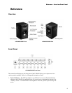
Reference - Rear Panel