


21
AC Power Connections
The LSR4300 voltage is set at the factory for use with either 100V-125V (U.S.) or
200V-250V. The ground terminal of the IEC plug is required by wiring codes and regulations.
It must always be connected to the electrical installation safety ground. CAUTION: Do not
use three-pin-to-two-pin AC adapters to defeat the ground.
The LSR4300-Series units have carefully designed internal grounding and balanced inputs
and outputs to reduce the possibility of ground loops (hum). If hum occurs, see Appendix C
on page 34 in this manual for suggested audio signal wiring, system grounding hints and other
preventive measures.
Network Connections and DIP Switch Settings
The Harman HiQnet™ networking technology employed by the LSR4300 enables a number
of unique capabilities. When speakers are interconnected using HiQnet, you can make
changes to all speakers in the system simply by adjusting the controls of any one speaker. For
example, turning on the power to one speaker causes them all to power up; similarly, by
changing the volume of one speaker, an equal volume change is made in all speakers.
HiQnet networking also allows RMC calibration for all speakers to be accomplished with the
push of a single button, with the supplied calibration microphone connected to a single
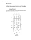
speaker. It also makes it possible for all speakers in the system to be controlled using the
supplied wireless remote control and/or LSR4300 Control Center Software. Up to eight
LSR4328P or LSR4326P speakers can be interconnected in a single network. HiQnet enables
coordinated RMC calibration so sound arriving at the mix position from all speakers is
precisely balanced.
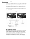
To network your LSR4300 system:
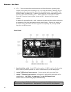
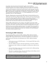
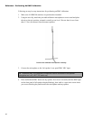
1. Interconnect all speakers using the supplied CAT5 cable. Plug one end of the cable into
either of the two HiQnet ports on one speaker and the other end into a HiQnet port on
another speaker until all speakers are connected. (Speakers can be connected in any order).
2. Place the two supplied Ethernet terminators on the first and last speakers in the chain.
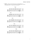
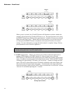
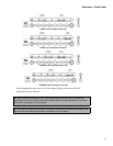
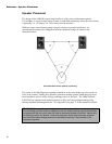
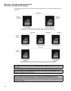
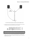
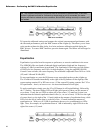
3. Finally, set each speaker’s rear panel DIP switches according to its position in the
system. For example, place the DIP switch labeled LEFT in the up (ON) position for the
speaker reproducing the left channel, and place the DIP switch labeled RIGHT in the up
(ON) position for the speaker reproducing the right channel. To set the DIP switch, gently
push the white plastic nub of using a small flat blade screwdriver, a toothpick or other
narrow object. Only one DIP switch should be in the up (ON) position.
Reference - AC Power Connections/Network
Connections and DIP Switch Settings