


23
Audio Connections
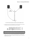
The LSR4328P and LSR4326P speakers are equipped to accommodate a range of analog and
digital signal input sources. You can connect two digital sources and one analog source to each
speaker and switch between them using front panel controls, or the wireless remote control
and/or LSR4300 Control Center software.
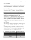
Analog Connections
Positive voltage to Pin 2 of the XLR connector or the tip of the ¼″ jack will produce a
forward motion in the speaker cone. See Appendix C in this manual for wiring diagrams.
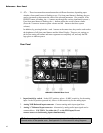
Analog signal sources must be connected to either the rear panel XLR or ¼″ connector.
Do not connect analog signal to both the XLR and ¼″ inputs; use one or the
other.
The LSR4300 provides switchable input sensitivity between +4 dBu and -10 dBV, as
determined by the two-position Input Sensitivity switch on the rear panel.
When the sensitivity is set for +4 dBu, an input signal equal to +4 dBu will produce a system
output level of 94 dB SPL at a distance of one meter. Likewise, a setting of –10 dBV will
cause an input level of –10 dBV to attain the output acoustic level of 94 dB SPL at a distance
of one meter. Use of the front panel Volume control (that is, pressing the +/- button when no
button is flashing) allows further level matching.
Incoming analog signal is internally routed to the LSR4300’s high resolution 96kHz, 24-bit,
oversampling A/D converters.
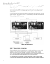
Digital Connections
Connect digital sources in AES/EBU format to the rear panel XLR digital input connector and
those in S/PDIF format to the rear panel phono digital input connector. The following sample
rates are supported: 96kHz, 88.2kHz, 48kHz, 44.1kHz, 32kHz, with word lengths of up to 24
Bits.
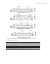
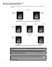
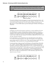
AES/EBU and S/PDIF digital audio is transmitted as a two-channel pair on a single cable.
Each LSR4300 speaker can reproduce only one channel at a time: either the left “A” channel
or the right “B” channel. The channel reproduced is determined by the speaker’s DIP switch
settings, as per the chart below. For example, when the leftmost (“Left”) DIP switch is ON,
the speaker will reproduce Channel A of the incoming stereo digital data stream.
When the following DIP Switch is in the ON position: The speaker will reproduce Channel:
LEFT A
RIGHT B
CENTER A
LEFT SURROUND A
RIGHT SURROUND B
CENTER SURROUND A
LEFT EXTRA A
RIGHT EXTRA B
Reference - Audio Connections