


36
Connecting
—Continued
• When several i.LINK components are connected
together, i.LINK may not work properly if certain
components are on standby. i.LINK will work prop-
erly while the RDV-1.1 is on standby. However, the
system will not work at all if any component is fully
shutdown (i.e., power switch set to off). Refer to the
manuals supplied with your other components for
more information.
• i.LINK operation may be interrupted if a connected
component is turned on or off, or its i.LINK settings
are turned on or off.
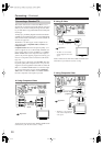
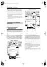
This section shows how to connect the RDV-1.1’s audio
outputs to an AV receiver’s audio inputs.
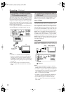
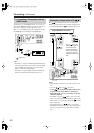
K. Digital Audio Connection
(Dolby Digital & DTS)
To fully enjoy the Dolby Digital and DTS soundtracks
available on most DVD-Video discs, you need to connect
one of the RDV-1.1’s digital audio outputs (DIGITAL 1
or DIGITAL 2) to a digital audio input on an AV receiver
that supports Dolby Digital and DTS. You can also enjoy
Dolby Surround, if your receiver supports Dolby Pro
Logic.
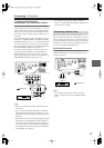
Use an optical, coaxial, or AES/EBU digital audio cable
to connect one of the RDV-1.1’s DIGITAL 1 (OPTI-
CAL, COAXIAL) or DIGITAL 2 outputs (OPTICAL,
COAXIAL, or AES/EBU) to a corresponding digital
audio input on your AV receiver, as shown.
Notes:
• Dolby Digital, DTS, DVD-Audio, and SACD can also
be fully enjoyed by using i.LINK (page 34).
• In addition to a digital connection, it’s recommended
that you also connect the D.MIX AUDIO OUT to a
spare analog audio input on your AV receiver, as this
will allow you to record audio to a cassette recorder or
CD recorder. If your AV receiver supports Zone 2, you
must make an analog audio connection in order to
select the RDV-1.1 as the input source for Zone 2.
• Make sure that the digital output (Digital 1 Out or Dig-
ital 2 Out) is set to Dolby Digital (see page 75). Oth-
erwise you won’t get surround sound. Likewise for
DTS (see page 75).
• When playing Dolby Digital or DTS soundtracks, be
sure to select Dolby Digital or DTS decoding, respec-
tively, on your AV receiver. Refer to your AV
receiver’s manual.
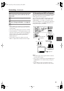
• The AES/EBU socket outputs digital audio, so do not
connect it to an analog audio input on another compo-
nent.
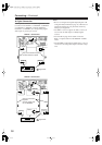
Connecting to an AV Receiver’s
Audio Inputs
COAXIAL OPTICAL OPTICALCOAXIAL
DIGITAL
1
DIGITAL
2
DIGITAL 2
(
BALANCED
)
AES/EBU
AUDIO
OUT
D. MIX FRONT SURR
1
CENTER SURR
2
L
R
L
R
IN
SUB
WOOFER
1
2
YPB PR
OUT
OUT
IN
REMOTE
CONTROL
VIDEO
OUT
COMPONENT
VIDEO
S
VIDEO VIDEO
S
VIDEO
Y
P
B
PR
Y
P
B
PR
IN
1
+
21
RS
232
HDMI
VIDEO
IN
IR
S400
(
AUDIO
)
AUDIO
OUT
HD VIDEO
OUT
COMPONENT
12
V
TRIGGER
SURR
MODE
(
AUDIO OUT
)
COAXIAL
COAXIAL IN
OPTICAL
OPTICAL IN
DIGITAL
1
DIGITAL
1
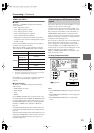
Signal flow
AV receiver
Only one connection
required!
Choose coaxial or opti-
cal
DIGITAL 1 Connections
COAXIAL OPTICAL OPTICALCOAXIAL
DIGITAL
1
DIGITAL
2
DIGITAL 2
(
BALANCED
)
AES/EBU
AUDIO
OUT
D. MIX FRONT SURR
1
CENTER SURR
2
L
R
L
R
IN
SUB
WOOFER
1
2
YPB PR
OUT
OUT
IN
REMOTE
CONTROL
VIDEO
OUT
COMPONENT
VIDEO
S
VIDEO VIDEO
S
VIDEO
Y
P
B
PR
Y
P
B
PR
IN
1
+
21
RS
232
HDMI
VIDEO
IN
IR
S400
(
AUDIO
)
AUDIO
OUT
HD VIDEO
OUT
COMPONENT
12
V
TRIGGER
SURR
MODE
(
AUDIO OUT
)
COAXIAL
COAXIAL IN
OPTICAL
OPTICAL IN
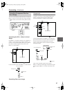
DIGITAL
2
DIGITAL 2
DIGITAL 2
(
BALANCED
)
AES/EBU
AUDIOOUT
AES/EBU IN
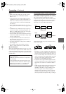
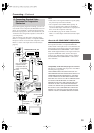
Signal flow
AV receiver
Only one connection
required!
Choose coaxial, optical,
or AES/EBU
DIGITAL 2 Connections