


19
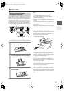
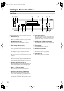
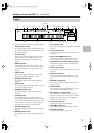
Getting to Know the RDV-1.1
—Continued
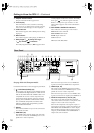
F
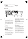
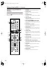
VIDEO IN S VIDEO (39)
This input accepts S-Video and can be connected to
an S-Video output on a satellite/cable tuner or other
component.
When the video input source is set to External,
video signals received here are upconverted to pro-
gressive video and output by the HD VIDEO OUT
COMPONENT 1 and 2 outputs.
G
VIDEO IN VIDEO (39)
This input accepts composite video and can be con-
nected to a composite video output on a satellite/
cable tuner or other component.
When the video input source is set to External,
video signals received here are upconverted to pro-
gressive video and output by the HD VIDEO OUT
COMPONENT 1 and 2 outputs.
H
VIDEO OUT COMPONENT (Y, P
R
, P
B
) (30)
These sockets output component video and can be
connected to a component video input on a TV or
projector. They output only interlaced video.
I
VIDEO OUT S VIDEO (30)
These two sockets output S-Video and can be con-
nected to an S-Video input on a TV or projector.
J
VIDEO OUT VIDEO (30)
These two sockets output composite video and can
be connected to a composite video input on a TV or
projector.
K
DIGITAL 1 AUDIO OUT (36, 38)
These sockets output digital audio and can be con-
nected to the digital audio input on a hi-fi amp, AV
receiver, surround sound decoder (Dolby Digital,
DTS), or other component. There’s a coaxial output
and an optical output.
L
DIGITAL 2 AUDIO OUT (36, 38)
These sockets output digital audio and can be con-
nected to the digital audio inputs on a hi-fi amp, AV
receiver, surround sound decoder (Dolby Digital,
DTS), or other component. There’s an AES/EBU
(balanced XLR) output, a coaxial output, and an
optical output.
M
IR IN/OUT (41)
The IR IN socket can be used to connect a commer-
cially available IR receiver, which can be used to
pickup signals from the remote controller when the
RDV-1.1 is located in another room, installed in a
rack, or is out of range of the remote controller
The IR OUT connector can be used to connect a
commercially available IR emitter, which can be
used to pass remote controller signals received by
the IR IN along to other components.
N
REMOTE CONTROL (40)
These (Remote Interactive) sockets can be con-
nected to the sockets on other Integra
RESEARCH AV components for interactive con-
trol.
To use you must make an analog audio connec-
tion between the RDV-1.1 and your Integra
RESEARCH AV receiver, even if they are con-
nected digitally.
O
D.MIX AUDIO OUT (30, 31, 37)
These sockets output analog audio and can be con-
nected to a stereo analog audio input on a TV, hi-fi
amp, or other component. If the source audio is
multichannel (Dolby Digital, DTS, DVD-Audio,
SACD), they output a 2-channel downmix.
P
FRONT, SURR 1, CENTER & SUBWOOFER
AUDIO OUT (37)
These sockets output 5.1-channel analog audio and
can be connected to a 5.1-channel analog audio
input on an AV receiver, surround sound decoder
(Dolby Pro Logic), or other component.
Q
SURR 2 AUDIO OUT (37)
These sockets output the same analog audio as the
SURR1 outputs and can be connected to the analog
surround back left and right inputs on a 7.1-channel
AV receiver or other component. When using these
sockets, the SURR MODE switch should be set to
1+2.
R
SURR MODE (AUDIO OUT) switch (37)
This switch is used to set the surround output mode
of the analog multichannel audio outputs. If you
connect the SURR 2 outputs to a 7.1-channel AV
receiver or amp, set this switch to 1+2. This reduces
the output level by 3 dB. If you’re not using the
SURR 2 outputs, set this switch to 1.
S
HD VIDEO OUT COMPONENT 1 (31)
These BNC sockets output HD component video
and can be connected to the HD component video
input on an HDTV or projector. If you input HD
video to the component VIDEO IN socket, this out-
put should be connected to the HDTV or projector.
When an SD video signal is fed to a VIDEO IN
socket (component, S-Video, or composite), and the
video input source is set to External, that video sig-
nal is upconverted to progressive and output here.
When an HD video signal is fed to the component
VIDEO IN socket, and the video input source is set
to External, that HD video signal is output here at
the same resolution.
T
HD VIDEO OUT COMPONENT 2 (31)
These BNC sockets output HD component video
and can be connected to the HD component video
input on an HDTV or projector.
When an SD video signal is fed to a VIDEO IN
socket (component, S-Video, or composite), and the
video input source is set to External, that video sig-
nal is upconverted to progressive and output here.
When an HD video signal is fed to the component
VIDEO IN socket, and the video input source is set
to External, nothing is output by these sockets.