


4 - 2
16
R3V
X1
Q51, Q52
1110
FM IF IC (IC15)
• 2ND IF DEMODULATOR CIRCUIT
9
1312
“NOISE” signal to the CPU (IC4, pin 47)
1st IF signal from the 1st mixer (IC16, pin 6)
“RSSI” signal to the CPU (IC4, pin 4)
2
8
735
LPF
BPF
(WFM)
(FM)
RSSI
Noise
Detector
Noise
Amplifier
Limitter
Amplifier
Quodrature
Detector
FI1
2nd IF signal to the AM demodulator (Q19, Q20)
FM-demodulated signals
to the AF circuits
X2
TCXO
L103
D12
D10
15.3/45.9 MHz
2nd LO signal
Q29
LPF
HPF
D51
×1
D52
×3
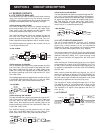
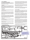
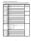
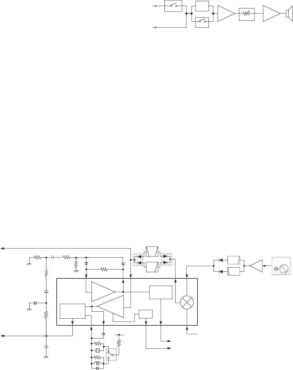
4-1-3 2ND IF AND DEMODULATOR CIRCUITS
(MAIN UNIT)
The 1st IF signal is converted into the 2nd IF signal and
demodulated in the FM IF IC. The FM IF IC contains 2nd
mixer, limiter amplifier, quadrature detector, etc. in its
package.
The 1st IF signal from the 1st IF amplifi er (Q9) is applied to
the 2nd mixer in the FM IF IC (IC15, pin 16), and converted
into the 2nd IF signal by being mixed with the 2nd LO signal
from the reference frequency oscillator (X2) tripled by the
tripler (Q29).
The converted 2nd IF signal is output from pin 3, and passed
through the 2nd IF filter via the FM/WFM switch (D12) to
suppress sideband noise.
• FM/WFM mode
In FM mode, the 2nd IF signal is passed through the BPF (FI1).
In WFM mode, the signal passed through the LPF (L2, C136).
The filtered 2nd IF signal is applied to the limiter amplifier
in the FM IF IC (pin 5) via the FM/WFM switch (D10). The
amplifi ed 2nd IF signal is FM-demodulated at the quadrature
detector section and output from pin 9. The demodulated AF
signals are applied to the AF amplifi er circuits.
• AM mode
The 2nd IF signal is passed through the FI1 and applied to
the AM demodulator circuit (Q19, Q20). The demodulated AF
signals are applied to the AF amplifi er circuits.
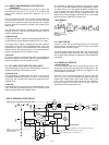
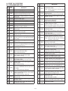
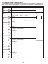
4-1-4 AF AMPLIFIER CIRCUITS (MAIN UNIT)
The demodulated AF signals from the demodulator circuits are
amplifi ed and fi ltered in AF amplifi er circuits.
• FM/WFM mode
The demodulated AF signals from the FM IF IC (IC15, pin 9)
are passed through the AF switch (IC14, pins 1,2) and AF fi lter
circuit (Q10, D5). The fi ltered AF signals are applied to the AF
amplifi er (Q12).
• AM mode
The demodulated AF signals from the AM-demodulator circuit
(Q19, Q20) are passed through the AF filter bypass switch
(Q28) and applied to the AF amplifi er (Q12).
The amplified AF signals are applied to the electric volume
(IC7, pin 11) and level adjusted. The level adjusted AF signals
are output from pin 12, and applied to the AF amplifi er (IC9,
pin 2) to obtain more than 50 mW of AF output power. The
power amplified AF signals are then output from pin 6, and
applied to the internal speaker (CHASSIS; SP1) or connected
external speaker via [MIC/SP] connector (J4).
4-1-5 AGC CIRCUIT
A portion of the AM-demodulated signals are converted
into DC voltage, and fed back to the RF circuits as the AGC
(Automatic Gain Controller) signal.
The AGC signal controls the bias of the 1st IF amplifi er (Q9)
and RF amplifi ers (Q38, Q39, Q42, Q43, Q45) according to
the received signal strength to stabilize the demodulated AF
signal level.
4-1-6 SQUELCH CIRCUITS
• NOISE SQUELCH
The noise squelch mutes the AF output signals when no RF
signals are received. By detecting noise components in the
demodulated AF signals, the squelch circuit toggles the AF
power amplifi er ON and OFF.
A portion of the FM-demodulated AF signals from the
FM IF IC (IC15, pin 9) are passed through the noise filter
(R186, R187, R192, R196, R197, R204, C150, C152, C158,
C162, C164). The fi ltered noise signals are then applied to
the noise amplifier in the FM IF IC (IC15, pins 7, 8) to be
amplifi ed the noise components only.
• AF CIRCUITS
IC14
from
the FM IF IC
(IC15, pin 9)
from the
AM demodulator circuit
(Q19, Q20)
IC7
11 12 2 6
AF switch
Ele. VR
Q12
Q28
12
Q10, D5
AF
Amp.
Power
Amp.
IC9
Speaker
AF
Filter
bypass