


5 - 4
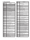
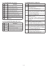
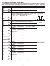
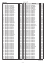
ADJUSTMENT ITEM
ADJUSTMENT CONDITION
VALUE
DTCS LEVEL
(VHF)
[dt1]
1
• Push [CALL] (No adjustment)
−
(UHF)
[dt2]
2
• Push [CALL] (No adjustment)
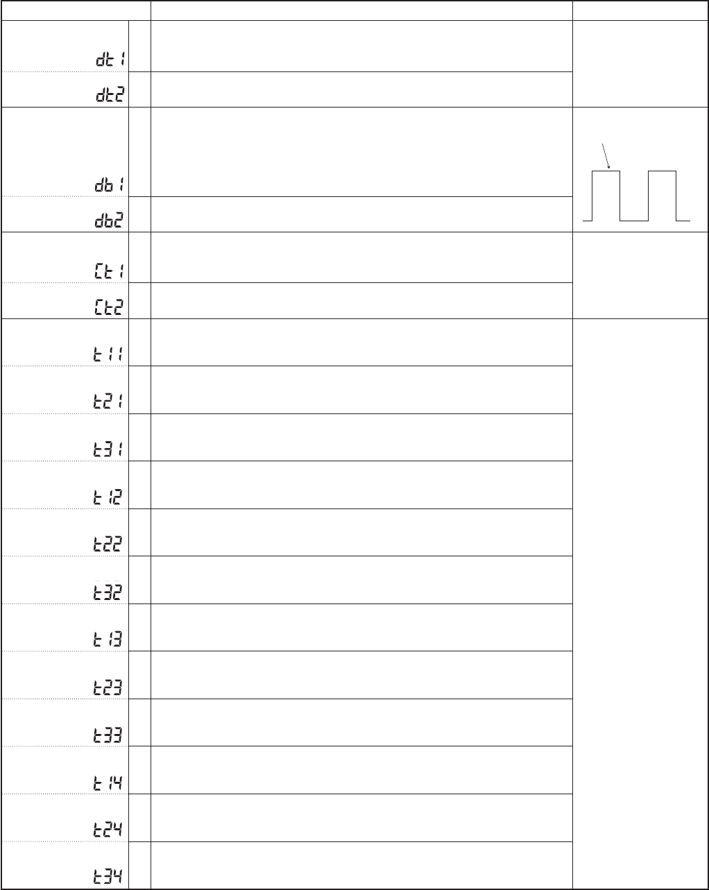
DTCS BALANCE
(VHF)
[db1]
1
•
•
•
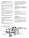
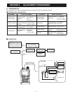
No audio signal is applied to the [MIC/SP] jack.
Connect a modulation analyzer with an osciloscope to the antenna connec-
tor through an attenuator, and set the modulation analyzer as;
HPF : OFF
De-emphasis
: OFF
LPF : 20 kHz
Detector
: (P–P)/2
Transmitting
Set to square wave
form
(UHF)
[db2]
2
• Transmitting
CTCSS DEVIATION
(VHF)
[Ct1]
1
•
•
•
No audio signal is applied to the [MIC/SP] jack.
Set the modulation analyzer as the same as "
DTCS BALANCE".
Transmitting
±0.75 kHz
(UHF)
[Ct2]
2
• Transmitting
RX SENSITIVITY
[t11]
1
•
•
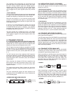
Connect an SSG to the antenna connector and set as;
Frequency : Specifi ed frequency* Level : 0 dBµ
†
(−107 dBm)
Receiving
Push [FUNC]+[BAND]
(Automatic adjustment)
[t21] 2
•
•
Set the SSG as;
Frequency : Specifi ed frequency*
Receiving
[t31] 3
•
•
Set the SSG as;
Frequency : Specifi ed frequency*
Receiving
[t12] 4
•
•
Set the SSG as;
Frequency : Specifi ed frequency*
Receiving
[t22] 5
•
•
Set the SSG as;
Frequency : Specifi ed frequency*
Receiving
[t32] 6
•
•
Set the SSG as;
Frequency : Specifi ed frequency*
Receiving
[t13] 7
•
•
Set the SSG as;
Frequency : Specifi ed frequency*
Receiving
[t23] 8
•
•
Set the SSG as;
Frequency : Specifi ed frequency*
Receiving
[t33] 9
•
•
Set the SSG as;
Frequency : Specifi ed frequency*
Receiving
[t14] 10
•
•
Set the SSG as;
Frequency : Specifi ed frequency*
Receiving
[t24] 11
•
•
Set the SSG as;
Frequency : Specifi ed frequency*
Receiving
[t34] 12
•
•
Set the SSG as;
Frequency : Specifi ed frequency*
Receiving
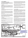
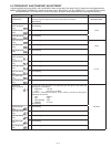
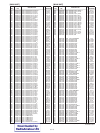
5-3 SIGNALING AND RECEIVE ADJUSTMENT
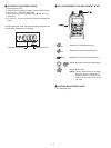
• Set the specifi ed value using [DIAL], and push [BAND] to store the set value. Then, push [CALL] to move to the next adjustment item.
NOTE: "DTCS BALANCE" should be adjusted before "CTCSS DEVIATION," and "RX SENSITIVITY" should be adjusted before
"FM/WFM S-METER" (on the next page).
Otherwise, these adjustments will not be adjusted properly.
*Displayed on the function display.
†
The output level of the standard signal generator (SSG) is indicated as the SSG’s open circuit.