


14 INSTALLATION AND CONNECTIONS
Installation and Connections
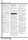
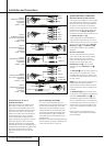
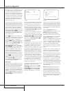
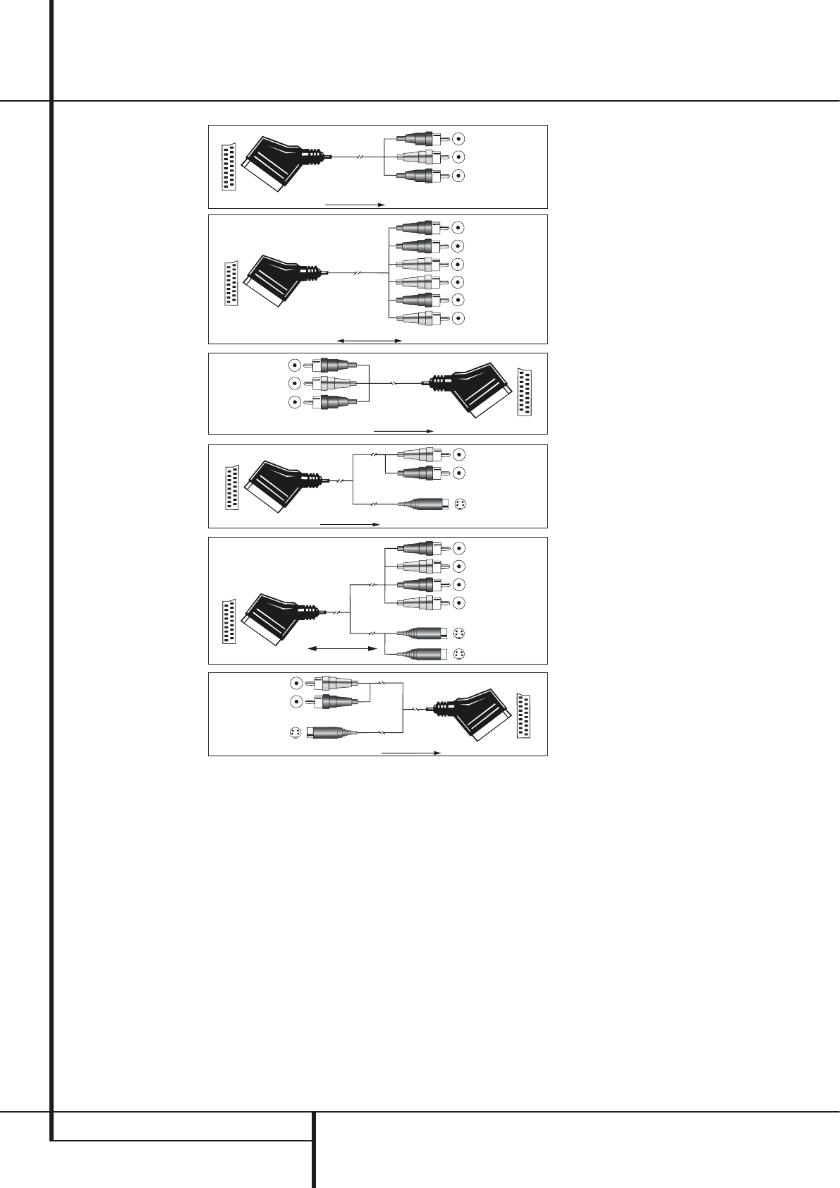
Figure 1:
SCART/Cinch-Adapter
for playback;
signal flow:
SCART → Cinch
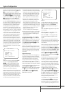
Figure 2:
SCART/Cinch-Adapter
for record and playback;
signal flow:
SCART ↔ Cinch
Figure 3:
Cinch/SCART-Adapter for
playback;
signal flow:
Cinch → SCART
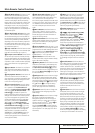
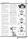
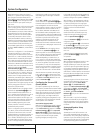
Figure 4:
SCART/S-Video Adapter
for playback;
signal flow:
SCART → Cinch
Figure 5:
SCART/S-Video Adapter
for record and playback;
signal flow:
SCART ↔ Cinch
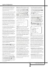
Figure 6:
SCART/S-Video Adapter
for playback;
signal flow:
Cinch → SCART
Black
Yellow
Red
Black
Red
Blue
1
Yellow
Green
1
White
Black
Yellow
Red
Red
Black
S-Video In
Red
Black
S-Video Out
Black
Red
Blue
1
Yellow
S-Video In
S-Video Out
1
Also other colours possible, e.g. brown and grey.
Important Note for the Use of
SCART-Cinch Adapters:
When video sources are connected to the TV
directly with a SCART cable, specific control
signals apart from Audio/Video signals will be
fed to the TV.These specific signals are:With all
video sources, the signal for automatic input
selection that switches the TV automatically to
the appropriate input as soon as the video
source is started.And with DVD players, the
signals automatically turning the TV to 4:3/16:9
format (with 16:9 TVs or with 4:3 TVs with
selectable 16:9 format) and turning the RGB
video decoder of the TV on or off, depending on
the DVD player´s setting.With any adapter cable,
these control signals will be lost and the
appropriate setting of the TV must be made
manually.
Note for RGB signal with SCART:
If you use a unit providing RGB signals on a
SCART output (as e.g. most DVD players do) and
you want to use that RGB signal, this SCART
output must be connected directly to your TV.
Although the AVR can switch three-way video
signals (like component signals Y/Pb/Pr), most
TVs need separate sync signals for RGB (also
with SCART) that cannot be switched and pro-
vided by the AVR.
RGB signals can be pathed through the AVR only
when no separate sync signal is needed (see last
”Video Connection Note” on page 13).
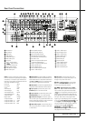
System and Power Connections
Main Room Remote Control Extension
If the receiver is placed behind a solid or smoked
glass cabinet door, the obstruction may prevent
the remote sensor from receiving commands. In
this event, the remote sensor of any Harman
Kardon or other compatible device, not covered
by the door, or an optional remote sensor may
be used. Connect the Remote IR Output of
that device or the output of the remote sensor to
the Remote IR Input jack
V
.
If other components are also prevented from
receiving remote commands, only one sensor is
needed. Simply use this unit’s sensor or a remote
eye by running a connection from the Remote
IR Output jack
U
to the Remote IR Input
jack on Harman Kardon or other compatible
equipment.
AC Power Connections
This unit is equipped with two accessory AC
outlets. They may be used to power accessory
devices, but they should not be used with
high-current draw equipment such as power
amplifiers. The total power draw to the
Unswitched Outlet
H
must not exceed
100 watts, that to the Switched Outlet
G
50 watts.
The Switched
G
outlet will receive power only
when the unit is on completely. This is recom-
mended for devices that have no power switch
or a mechanical power switch that may be left in
the “ON” position.
NOTE: Many audio and video products go into a
Standby mode when they are used with
switched outlets, and cannot be fully turned on
using the outlet alone without a remote control
command.
The Unswitched
H
outlet will receive power
as long as the unit is plugged into a powered AC
outlet and the Main Power Switch
1
is on.
The AVR draws significantly more current than
other household devices such as computers that
use removable power cords. For that reason, it is
important that only the cord supplied with the
unit (or a direct replacement of identical capaci-
ty) be used.
Once the power cord is connected, you are
almost ready to enjoy the AVR 240’s incredible
power and fidelity!