


VSC 150 • Installation and Operation
VSC 150 • Installation and Operation
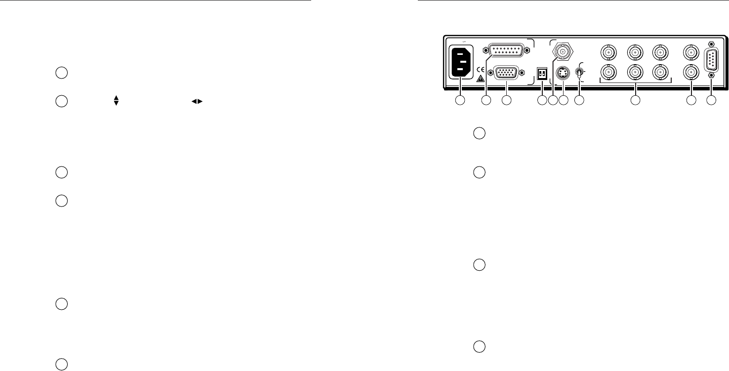
Installation and Operation, cont’d
1
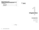
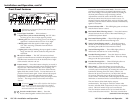
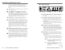
AC power input connector — Connect a standard IEC AC
power cord here for power input (100VAC to 240VAC,
50/60 Hz).
2
VGA computer input/Macintosh local monitor output
connector — Connect a VGA-type computer to the
VSC 150 via this 15-pin D connector (and the provided
Mac-VGA cable) to use a VGA-type computer as the video
signal source.
If a Macintosh, instead of a VGA-type PC, is used as a
source, this connector serves as the Mac local monitor pass-
through output connector.
3
Macintosh (Mac) input/VGA local monitor output
connector — Connect a Macintosh computer to the
VSC 150 via this 15-pin HD connector (and the provided
Mac-VGA cable) to use a Mac as the video signal source.
If a VGA/SVGA-type computer, instead of a Macintosh, is
used as a source, this connector serves as the VGA local
monitor pass-through output connector.
4
DIP switches — These two switches select the signal
standard (NTSC or PAL) applied to the scan converted
video output, and the video input termination (75 ohm or
high impedance).
1 — PAL Out — Select the output standard with this
switch. This switch affects both of the display outputs
(composite video and one other), but not the local
monitor.
ON — The output is in PAL (Phase Alternate Line)
format (625 lines/frame at 50 Hz vertical,
15.625 kHz horizontal).
OFF — The output is in NTSC (National Television
Standards Committee) format
(525 lines/frame at 60 Hz vertical, 15.734 kHz
horizontal).
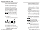
Rear Panel Features
50/60 Hz
100-240 V 0.3A
S-VIDEO
R-Y/B-Y/Y
RGB
R/R-Y
HVS
G/Y B/B-Y
RS-232
OUT
IN
GENLOCK
S-VIDEO
PAL OUT
75 OHM
VIDEO
MAC
VGA
I
N
P
U
T
S
O
U
T
P
U
T
S
5
3 62 8
9
104 71
(Continued)
2-7
default to the standard centering and pan functions. To
turn the size feature off, press the Size button again.
See Freeze control (3) for information on using Executive
mode.
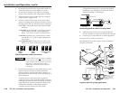
12
Size control LED — This LED lights green to indicate that
the size feature is active.
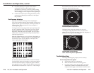
13
Vertical ( ) and horizontal ( ) Centering/Pan/Size
rotary controls — Turn these knobs to adjust vertical or
horizontal centering (when the image size does not exceed
screen size) and panning (when the image size exceeds the
screen size) in the regular mode. Rotate these controls to
adjust picture size when the Size mode is active.
14
Min/Max LED — This lights red when the minimum or
maximum limit of a control (13) has been reached.
15
Burst Lock (genlock) LED — This lights green to indicate
that the VSC 150 is receiving a genlock (black burst) sync
signal via the rear panel genlock input connector. Genlock
is a sync timing reference signal used to synchronize an
entire system’s components. If this LED does not light
when genlock is active, then either further phase
adjustment is needed, or a different, more stable or time-
base-corrected sync signal must be used for the genlock
source.
16
Horizontal phase (Horz Phase) control — During genlock
setup use a small screwdriver to rotate this control to align
the horizontal phase of the composite video sync signal
with that of the genlock signal. See “Setting Up Genlock
and Vertical Interval Switching” in this chapter for details.
17
Subcarrier phase (Sub Phase) control — During genlock
setup use a small screwdriver to rotate this control to align
the color subcarrier phase of the composite video sync
signal with that of the genlock signal. See “Setting Up
Genlock and Vertical Interval Switching” in this chapter for
details.
2-6