


VSC 150 • Installation and Operation
VSC 150 • Installation and Operation
Installation and Operation, cont’d
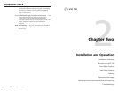
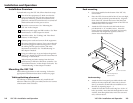
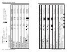
configuration, the last device must provide genlock
termination. See “Setting Up Genlock and Vertical
Interval Switching” in this chapter.
VSC 150
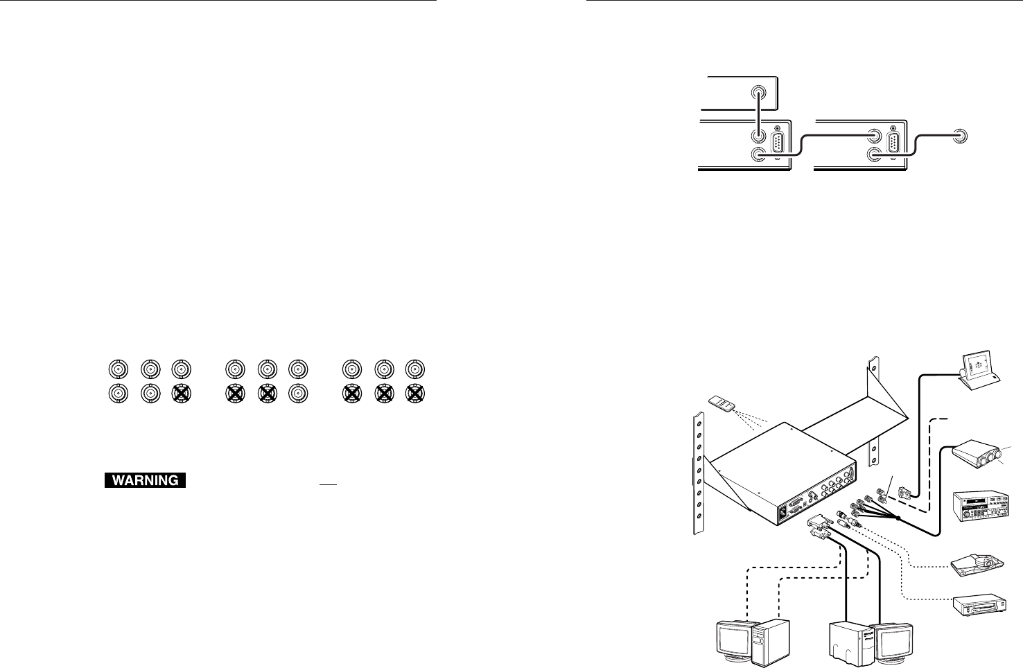
Rear Panel
VSC 150
or Other Device
To Next Device
or Terminate
Timing Source
OUT
RS-232
OUT
IN
GENLOCK
RS-232
OUT
IN
IN
GENLOCK
Connecting genlock cables in a daisy chain
8. If RS-232 control will be used, connect the RS-232
remote controller or computer to the RS-232 connector.
9. Connect power cords and turn on all the equipment.
The system is now ready for operation.
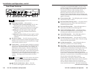
The illustration below shows typical system installation
and cable connections.
Videoconferencing
System
Only one S-video or component
video or RGB device may be
connected in addition to the
composite video device and
local monotor.
VCR
NOTE:
or
External Genlock
Timing
Terminator
Outputs
Video Outputs
Projector (RGBHV)
Video Editor
(Component)
RS-232 Control
Infrared System
Remote
Composite
Video
S-video
or
VGA Input
Mac Input
VSC 150
H
i
C
a
r
o
l
H
i
C
a
r
o
l
5
0/60 H
z
10
0-24
0 V
0.3A
S-VIDEO
R-Y/B-Y/Y
RGB
R/R-Y
H
V
S
G/Y B/B-Y
RS-232
OUT
IN
GENLOCK
S-VIDEO
PAL OUT
75 OHM
VIDEO
MAC
VGA
I
N
P
U
T
S
O
U
T
P
U
T
S
A typical VSC 150 system application
2-11
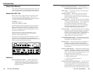
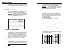
3. Set the PAL Out (NTSC/PAL output) DIP switch. Use
“Rear Panel Features” in this chapter as a guide.
4. Connect the composite video display or recording
device to the composite video output BNC connector.
5. Select the format of the second output by setting the
output selection toggle switch.
6. Connect a cable from the input of the second video
display/recording device (projector, monitor, VCR) to
the appropriate VSC 150 rear panel output connectors.
For S-video, connect the cable to the 4-pin mini-DIN
connector.
For RGBHV (separate H and V sync) output, connect
coaxial cables to the BNC connectors labeled
R/R-Y, G/Y, B/B-Y, H and V, as shown below.
For RGBS (composite sync), connect the coax cables
to the R/R-Y, G/Y, B/B-Y, and S connectors, as
shown below.
For component video, connect the coax cables to the
R/R-Y, G/Y, B/B-Y connectors as shown below.
R/R-Y
HVS
G/Y B/B-Y R/R-Y
HVS
G/Y B/B-Y R/R-Y
HVS
G/Y B/B-Y
RGBHV
output
RGBS
output
Component video
output
Video output BNC cable connections
Connect cables for only one output in addition
to the composite video output. Do not connect
cables to outputs that will not be used for your
application. Connecting cables to more
outputs will overload the circuits and yield
weak signals.
7. Connect the coax cable from the genlock device (or the
genlock output of another device that shares the
genlock signal) to the Genlock In BNC connector. If
no genlock device will be used, do not attach cables to
these connectors.
If another device in the system will use genlock,
connect the device to the Genlock Out BNC connector
of the VSC 150 as shown in the illustration on the next
page. Otherwise, attach a termination adapter to the
Genlock Out connector. If the genlock signal is
connected to several devices in a daisy chain
2-10