


VSC 150 • Installation and Operation
VSC 150 • Installation and Operation
Installation and Operation, cont’d
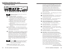
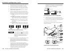
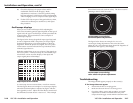
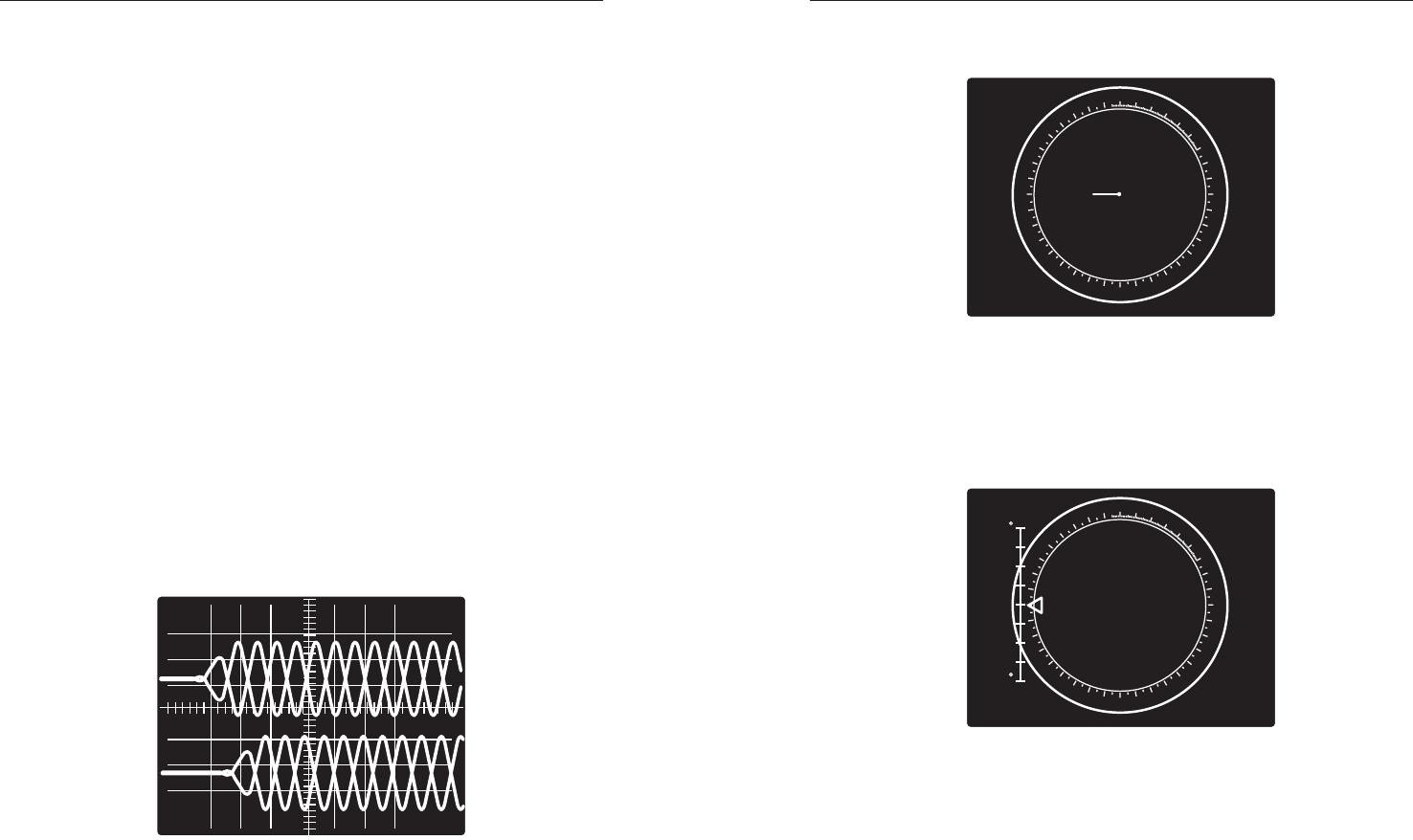
shows black burst only (with no color). The burst vector is
pointing to the left from the center.
0
10
20
30
40
50
60
70
80
90
100
110
120
130
140
150
160
170
180
190
200
210
220
230
240
250
260
270
280
290
300
310
320
330
340
350
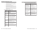
Vectorscope screen during
horizontal phase adjustment
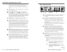
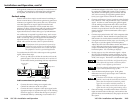
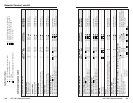
The figure below shows an example of a view of a
vectorscope during adjustment of the color subcarrier
phase (SC/H). The subcarrier phase should be aligned to 0º
(indicated in the figure by the triangle).
0
10
20
30
40
50
60
70
80
90
100
110
120
130
140
150
160
170
180
190
200
210
220
230
240
250
260
270
280
290
300
310
320
330
340
350
+40
-40
A1
A2
A3
B1
B2
B3
Vectorscope screen during
color subcarrier phase adjustment
Troubleshooting
The image should appear properly on the screen(s).
If the image does not appear
1. Ensure that all devices are plugged in.
2. Make sure that each device is receiving power.
3. Check the cabling, wiring and grounding, and make
adjustments as needed. Ensure that the rear panel
output selection toggle switch and PAL Out DIP switch
2-17
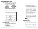
10. Check the display(s) for proper colors and for
undesirable artifacts in the image(s). Make
adjustments as necessary. Once the genlock timing
has been adjusted, it should not require readjustment
when changing to a new computer video signal input.
11. If other VSC 150s are part of this genlock daisy chain,
connect the oscilloscope to each device, and repeat
this procedure.
Oscilloscope displays
What you see on the oscilloscope while adjusting the
VSC 150 to match the genlock signal depends on the type of
signal used, the type of oscilloscope, and the procedure the
scope requires. This section shows some examples of
oscilloscope displays.
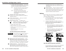
The figure below shows the genlock input signal (top) and
an out-of-alignment NTSC composite sync output signal
(bottom) displayed on a waveform monitor to check for
alignment. When the phases are aligned, the wave peaks
on the bottom waveform should line up with those in the
reference signal above it.
With this method there is no way to know if the signals are
180º out of phase. A delayed sweep on a time-based scope
would allow a more accurate display of the input and
output signal phase relationships.
Superimposed waveforms
A vectorscope is more accurate than a waveform monitor.
The next figure shows an example of a vectorscope display
when the horizontal phase is adjusted to align it with the
burst (genlock) vector. Adjust the Horz Phase control until
the difference between the two vectors is 0º. This example
2-16