


VSC 150 • Installation and Operation
VSC 150 • Installation and Operation
Installation and Operation, cont’d
2-3
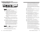
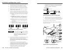
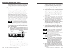
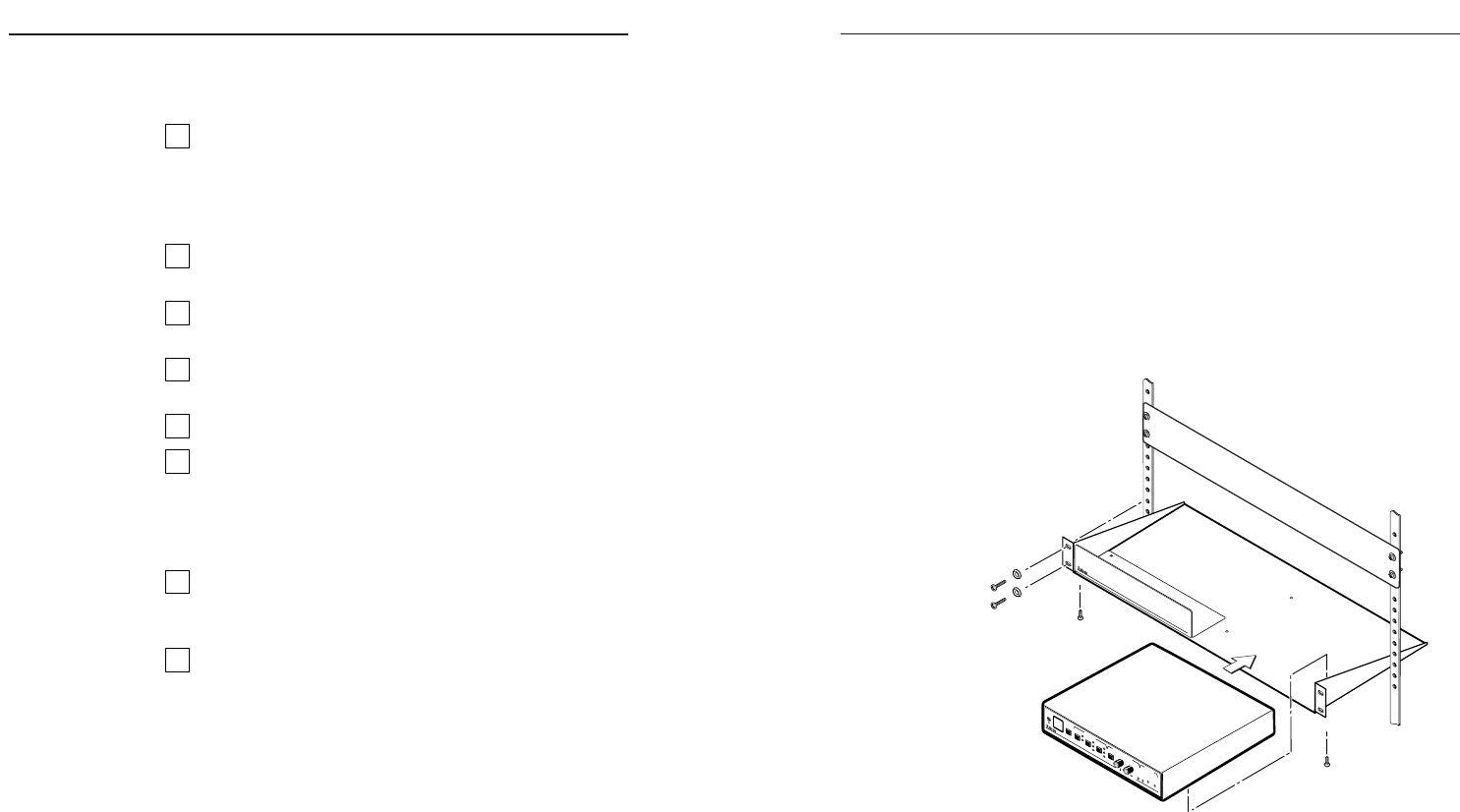
Rack mounting
1. If feet were installed on the bottom of the VSC 150,
remove them.
2. Place the VSC 150 on one half of the 1U (one unit high,
one unit wide) rack shelf (part #60-190-01). Align the
front of the VSC 150 with the front of the shelf, and
align the threaded holes on the bottom of the VSC 150
with the holes in the rack shelf.
3. Attach the VSC 150 to the rack shelf with the two
provided 4-40 x 1/8” machine screws. Insert the
screws from the underside of the shelf, and securely
fasten them into diagonally-opposite corners as
shown in the illustration below.
(2) 4-40 x 1/8" Screws
Use 2 mounting holes on
opposite corners
False front panel
uses 2 front holes
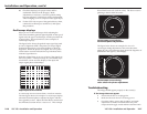
M
IN
/
M
A
X
B
U
R
S
T
L
O
C
K
H
O
R
Z
P
H
A
S
E
S
U
B
P
H
A
S
E
F
R
E
E
Z
E
S
IZ
E
H
O
R
Z
I
II
V
E
R
T
I
I
I
I
I
I
E
N
C
O
D
E
R
I
I
I
III
VSC 150
S
C
A
N
C
O
N
V
E
R
T
E
R
F
IL
T
E
R
IN
G
G
E
N
L
O
C
K
C
E
N
T
E
R
IN
G
/P
A
N
S
IZ
E
Rack mounting
4. Attach the false front panel (provided with the rack
shelf) to the unoccupied side of the rack (as shown
above), or install a second half-rack-width device in
that side by repeating steps 1 – 3.
5. Attach the rack shelf to the rack using four 10-32 x ¾”
bolts (provided). Insert the bolts through #10 beveled
washers, then through the holes in the rack ears and
rack, as shown above.
Installation and Operation
Installation Overview
To install and set up the VSC 150, follow these basic steps:
1
Turn all of the equipment off. Make sure that the
source computer, the VSC 150, the output devices
(projector, monitors), genlock device (black burst
generator), and remote control devices are turned off
and disconnected from the power source.
2
Mount the scan converter. See “Mounting the
VSC 150” in this chapter.
3
Set the rear panel toggle and DIP switches. See “Rear
Panel Features” in this chapter for details.
4
Attach the cables. See “Cabling” and “Rear Panel
Features” in this chapter.
5
Connect power cords and turn on all the equipment.
6
The image should now appear. If not, ensure that all
devices are plugged in and receiving power. Check
the cabling and rear panel switches, and make
adjustments as needed. See “Troubleshooting” in
this chapter if needed.
7
Using an oscilloscope, set up and adjust the genlock
signal. See “Setting Up Genlock and Vertical Interval
Switching” in this manual.
8
Adjust filtering and other settings from the front
panel buttons, or RS-232 or IR remote controller. See
“Front Panel Features” in this chapter for details. See
“Troubleshooting” in this chapter if needed.
Mounting the VSC 150
Select tabletop placement or rack mounting. Follow the
appropriate installation instructions on these two pages.
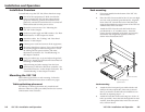
Tabletop/desktop placement
For tabletop or desktop placement only, install the self-
adhesive rubber feet/pads (provided) onto the four corners
of the bottom of the enclosure.
2-2