


VSC 150 • Installation and Operation
VSC 150 • Installation and Operation
Installation and Operation, cont’d
Cabling
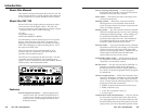
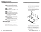
Attach cables to the scan converter as detailed in the steps
below. A diagram on page 2-11 shows how the system
looks when cabling is finished.
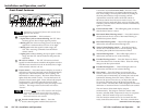
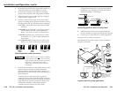
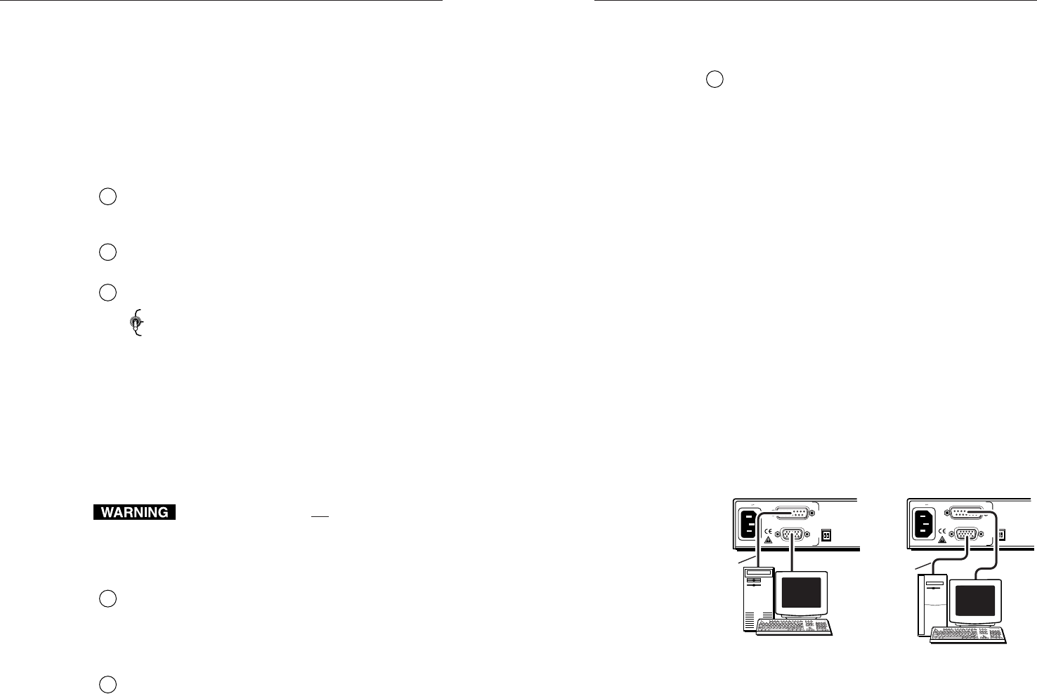
1. Connect the local monitor via its video input cable to
the corresponding (Mac or VGA) “input” connector
on the VSC 150’s rear panel.
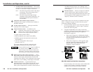
2. Using the included Mac-VGA cable, connect the
computer’s video output to the other input connector.
See the diagram below and the pin assignment
information on page 2-12.
• If the source computer is a Macintosh, plug the
VGA (15-pin HD) end into the VSC 150, and plug
the other (15-pin D) end into the computer’s
output connector.
• If the source computer is a VGA-type PC, plug
the Mac (15-pin D) end into the VSC 150, and
plug the other (15-pin HD) end into the
computer’s output connector.
50/60 Hz
100-240 V 0.3A
PAL OUT
75 OHM
MAC
VGA
I
N
P
U
T
S
50/60 Hz
100-240 V 0.3A
PAL OUT
75 OHM
MAC
VGA
I
N
P
U
T
S
PC Computer Mac Computer
Mac-VGA
cable
Mac-VGA
cable
Mac-VGA cable local monitor connections
If a local monitor will not be used, set the 75 Ohm DIP
switch to On (75 ohms), or install a termination
adapter on the unused local monitor connector.
2-9
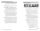
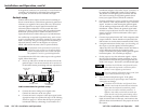
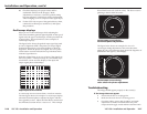
2 — 75 Ohm (video input termination) — This switch
provides a way to prevent blooming when no local
monitor or termination adapter is connected.
ON — The VSC 150 provides 75 ohm video input
termination. Select this setting when a
local monitor is not used.
OFF — The VSC 150 provides high Z (high
impedance) video input termination. Use
this setting when the system includes a
local monitor.
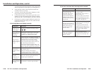
5
Composite video (Video) output connector —
Composite video output is continuously available on
this BNC connector.
6
S-video output connector — This 4-pin mini-DIN
connector is for S-video output.
7
Output selection switch — In addition to the
composite video output, one other output can
also be active. Choose from the following
formats via the output selection switch:
• S-video output (select S-video),
• RGBS (composite sync) output (select RGB),
• RGBHV (separate horizontal and vertical sync)
(select RGB), or
• Y, R-Y, B-Y (component video) output
(select R-Y/B-Y/Y).
The output cables must also be connected to the
appropriate connector(s) for the second output.
Connect cables for only one output in addition to
the composite video output. Do not connect
cables to outputs that will not be used for your
application. Connecting cables to more outputs
will overload the circuits and yield weak signals.
8
RGB/component video output connectors — These
BNC female connectors are for RGB output (red, green,
and blue video output; and horizontal, vertical, and
composite sync output), or for component video output
(R-Y, Y, B-Y). See “Cabling” in this chapter for details.
9
Genlock connectors — A genlock (black burst
generator) device can be connected to the VSC 150 via
these female BNC connectors to synchronize it with
other system components for seamless vertical interval
R-Y/B-Y/Y
RGB
S-VIDEO
2-8
switching between sources. See “Cabling” and
“Setting Up Genlock and Vertical Interval Switching”
in this chapter.
10
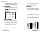
RS-232 connector — Connect a computer or RS-232
control module to this 9-pin D connector to allow
remote control using the Simple Instruction Set or the
Extron graphical control program for Windows. See
chapter 3, “Remote Control” for details.