


TP Receivers • Installation and Operation
Installation and Operation, cont’d
2-20
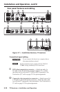
• The transmitter is receiving power from the
receiver, a local monitor is connected to the
transmitter, and the receiver output is connected to
a device that provides a reference ground.
• The receiver is connected through a TP switcher to
a device that provides a reference ground.
b
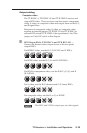
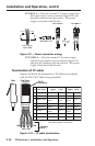
Manual/Auto switch (TP R BNC A and TP R BNC AV) — With
this switch in the Auto position, the receiver automatically
adjusts level and peaking to compensate for long cable runs. In
the Manual position, compensate for long cable runs using the
level and peaking controls.
N
If the transmitter is a VTT001, this switch should
always be set to Manual.
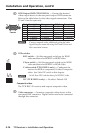
c
Auto LED (TP R BNC A and TP R BNC AV) — Indicates the
Manual/Auto switch is in the Auto position.
d
Level control — Adjusts the image brightness.
e
Peaking control — Adjusts the image sharpness.
N
For details on the SOG and C SYNC switches, see
Computer video earlier in this chapter.
Troubleshooting
If the image does not appear
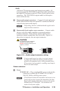
1. Ensure that all devices are receiving power. The
transmitter and receiver front panel Power LEDs indicate
they are receiving power.
2. Ensure the transmitter is receiving a video input.
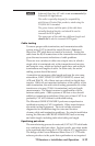
3. Ensure the TP cable(s) are properly terminated in
accordance with TIA/EIA T 568A standards and the RJ-45
connections are securely made. If the Power LEDs on the
transmitter and the receiver are lit green, a transmitter is
properly connected to a receiver.
4. For computer/RGB video, ensure the receiver SOG and
C Sync switches are in the correct positions for the video
output.
5. For computer video, ensure the transmitter ID bit switches
are on.
6. For computer video on an LCD projector, ensure the
transmitter DDSP (Digital Display Sync Processing) switch
is on.