


TP Receivers • Installation and Operation
Installation and Operation, cont’d
2-12
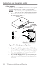
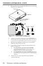
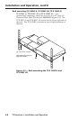
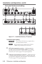
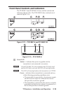
Rear panel features and cabling
TP R BNC A
TP R BNC AV
RGB INPUT
A-V INPUT
50/60 Hz
100-240V 0.3A
RGB OUTPUT
R
VIDEO
GBH/HV V
A
AUDIO
AUDIO
L
R
B
SOG
C SYNC
LR
A
A-V AUDIO
L
R
B
LR
RGB INPUT
RGB OUTPUT
RGB H/HV V
A
AUDIO
L
R
B
SOG
C SYNC
POWER
15V .5A DC
LR
TP R 15HD A
C SYNC
SOG
C VIDEO
N/C
LR
AUDIO
OUTPUT
AV INPUT
RGB
POWER
15V
.34A MAX
9
5
5
8
2 6 7 8 9
8
1
7
5
3
1 4 8 9
1
3
7
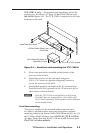
Figure 2-7 — Installation features, TP receivers
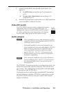
Transmitted signal cabling
C
Do not connect this device to a computer data or
telecommunications network
N
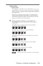
RJ‑45 termination must comply with the TIA/EIA
T 568A wiring standards for all connections.
a
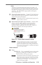
RGB video transmission connector — Attach one end of a
TP cable to this RJ-45 female connector (gure 2-7). Attach
the other end to an Extron TP 15HD or BNC transmitter. See
Termination of TP cable on page 2-15 for pin assignments.
b
Composite video transmission connector — Attach one end of
a TP cable to this RJ-45 female connector. Attach the other end
to an Extron TP composite video transmitter. See Termination of
TP cable on page 2-15 for pin assignments.