


TP Receivers • Installation and Operation
2-19
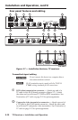
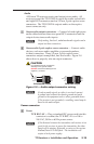
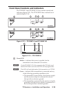
Front Panel Controls and Indicators
The TP R BNC A and TP R BNC AV have similar controls and
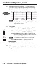
indicators (gure 2-12). The TP R 15HD A has a reduced set of
controls (gure 2-13).
TP R BNC A
RGB
MANUAL
AUTO
LEVEL PEAKING
1
3 4 5
2
TP R BNC AV
VIDEO
MANUAL
AUTO
LEVEL PEAKING
RGB
MANUAL
AUTO
LEVEL PEAKING
1
2 3 4 5
Figure 2-12 — TP R BNC A and TP R BNC AV
TP R 15HD A
RGB
PEAKING
LEVEL
1
4 5
Figure 2-13 — TP R 15HD A
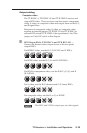
a
Power LED
Amber — indicates that power is applied, but the
transmitter is not connected to a receiver.
N
On the TP R BNC AV if the composite video TP link is used
and the RGB link is not used, this LED will only light amber.
N
This LED will only light amber if the transmitter is a VTT001.
Green — indicates that a transmitter is connected and any
of the following grounding conditions exist:
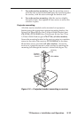
• The transmitter is powered by a local power supply
and the receiver output is connected to a device
that provides a reference ground.
• The transmitter is powered by the receiver, is locally
grounded, and the receiver output is connected to a
device that provides a reference ground.