


TP Receivers • Installation and Operation
Installation and Operation, cont’d
2-4
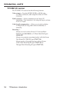
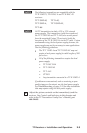
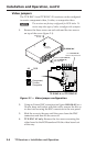
Video jumpers
The TP R BNC A and TP R BNC AV receivers can be congured
to receive component video, S-video, or composite video.
N
The receivers are factory configured for RGB video. To
receive any other type of video, reconfigure the jumpers.
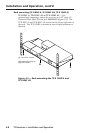
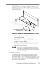
1. Remove the three screws on each side and the two screws
on top of the cover (gure 2-1).
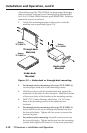
RGB
Bottom PC board (inside case)
TP R BNC A and TP R BNC AV
For TP R BNC AV
Remove Top PC board
J3
1
2
3
J3
U25
Component,
S-video,
Composite
J3
1
2
3
J3
RGB OUTPUT
RGB INPUT
A-V INPUT
A-V OUTPUT
AUDIO
R
VIDEO
G B
H/HV
V
A
AUDIO
L
R
B
A
L
R
B
ISOG
C SYNC
50/6
0 H
z
10
0-240
V 1
.3A
Lift Cover
Straight Up
TP R BNC AV
Remove 8
Screws
Remove 5 (TP R BNC A)
or 6 (TP R BNC AV)
BNC Hex Nuts
Figure 2-1 — Video jumper configuration
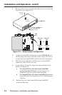
2. Using an Extron BNC extraction tool (part #100-096-01) or a
14 mm, deep well socket with thin walls, remove the ve or
six hex nuts securing the BNC connectors to the rear panel.
3. Slide the cover to the rear until the cover clears the BNC
connectors and then lift the cover off.
4. TP R BNC AV only: Remove the four screws securing the
video board to the RGB board and lift the video board out
of the way.