


TP Receivers • Installation and Operation
Installation and Operation, cont’d
2-14
d
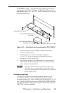
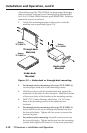
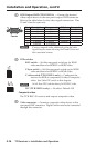
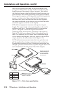
RGB Output 15HD (TP R 15HD A) — Connect the desired
video output device to the rear panel output 15HD connector.
Refer to the table below for the video signal connections. Pins
13 and 14 are for sync only.
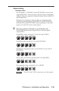
Pin# Description Component S-Video Composite
1 R R-Y C
2 G Y Y Y
3 B B-Y
6 R Return R-Y Return C Return
7 G Return Y Return Y Return Y Return
8 B Return B-Y Return
N
If using composite video, additional genlocked video
signals may be connected using the R and B lines and
their associated returns.
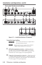
e
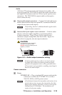
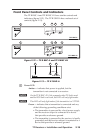
DIP switches
SOG switch — Set this rear panel switch up for RGsB
video and down for RGBHV or RGBS video.
C Sync switch — Set this rear panel switch up for RGBS
video and down for RGBHV or RGsB video.
C video switch (TP R 15HD A only) — Congures the
receiver for RGB or component/S-video/composite
video. See Video DIP switch in this chapter.
N
Set all three DIP switches down for RGBHV video.
N/C (TP R 15HD A only) — No effect. Default: Off
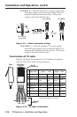
Composite video
The TP R BNC AV receives and outputs composite video.
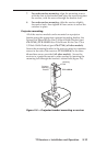
f
Video connector — Connect a composite video device to this
rear panel BNC connector. Digital audio can also be connected
through this connector.
51
15 11
610
Female
SOG
C SYNC
C SYNC
SOG
C VIDEO
N/C
ON