


TP Receivers • Installation and Operation
2-15
Audio
All Extron TP receivers receive and output stereo audio. All
receivers except the TP R 15HD A output the audio on both left
and right RCA connectors and on 3.5 mm, 5-pole captive screw
connectors. The TP R 15HD A outputs audio on the captive
screw connector only.
g
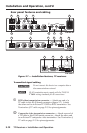
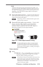
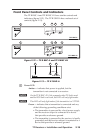
Stereo audio output connectors — Connect left and right stereo
audio cables between these rear panel RCA connectors and the
output device stereo audio inputs.
N
Only analog, line level, unbalanced audio signals can be
output on these connectors.
h
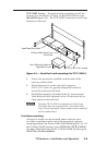
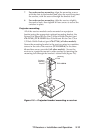
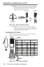
Stereo audio 5-pole captive screw connector — Connect audio
devices, such as an audio amplier or powered speakers,
to these connectors. These 3.5 mm, 5-pole captive screw
connectors output unamplied, line level audio. Figure 2-8
shows how to properly wire an output connector.
Tip
NO Ground Here
Sleeve(s)
Tip
NO Ground Here
Tip
Ring
Sleeve(s)
Tip
Ring
Unbalanced Output Balanced Output
L R
AUDIO
L R
AUDIO
CAUTION
For unbalanced audio, connect the
sleeve(s) to the ground contact.
DO NOT connect the sleeve(s) to the
negative (-) contacts.
Figure 2-8 — Audio output connector wiring
N
If only an audio signal, no video, is received, connect
a ground wire between the chassis ground and earth
ground in the equipment rack or other grounded device.
If the receiver is not grounded, a crackling sound may be
heard in the audio output.
Power connector
i
Power
TP R BNC AV — Plug a standard IEC power cord into this
connector to connect the TP R BNC AV to a 100 to
240 VAC, 50 Hz or 60 Hz power source.
N
If the distance between the transmitter and receiver is too
great for the receiver to power the transmitter, the video
image will be missing, distorted, or noisy, or the receiver
Manual/Auto LED will flash. The transmitter will
require a local power supply.