


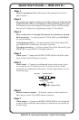
RGB 201 Rxi Universal Interface • Quick Start Guide
Quick Start Guide — RGB 201 Rxi, cont’d
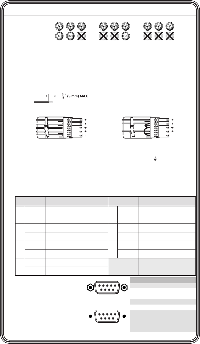
Pin RS-232 Function
1—
2TX Transmit data (-)
3RX Receive data (+)
4—
5 Gnd Signal ground
6—
7— —
8— —
9— —
—
—
—
Female
51
96
Male
15
69
RGBHV
R
H
G
V
B
S
RGBS
R G
S
B
VH S
RGsB
RsGsBs
R G B
VH
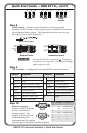
Step 8
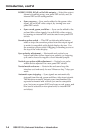
Audio output — Connect an audio device, such as powered
speakers, to this 3.5 mm, 5-pole captive screw connector for balanced
or unbalanced audio output. The gure below shows how to wire
the captive screw audio connector.
Balanced Audio
Tip
Ring
Tip
Ring
L R
Sleeves
Do not tin the wires!
Unbalanced Audio
Tip
Sleeve
Sleeve
Tip
L R
C
Connect the sleeve(s) to ground ( ). Connecting
the sleeve(s) to a negative (-) terminal will damage
audio output circuits.
Step 9
DIP switches — Congure the rear panel DIP switches as shown:
Switch Position Switch Position
1 Up DDSP, no sync processing 5 Up Mono on left channel
Down ADSP Down Stereo audio
2 Up RGsB or RsGsBs output 6 Up LCD backlight off
Down RGBHV or RGBS output Down LCD backlight on
3 Up Serration pulses 7 Up ID bits 4 & 11 grounded
Down No Serration pulses Down ID bits unterminated
4 Up Narrow V sync pulse 8 Spare
Down Wide V sync pulse
Step 10
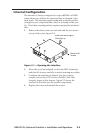
Remote connector —
Connect an RS-232 device
to this connector for
remote control. See
chapter 3, Remote Control
for details about SIS
commands and the control
software that is included with the interface.