


RGB 201 Rxi Universal Interface • Installation and Operation
2-5
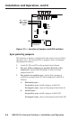
Internal sync DIP switches (RsGsBs)
The interface is factory congured to strip all sync signals from
the red, green, and blue video input signals and to output
horizontal and vertical sync separately(RGBHV) or as composite
sync (RGBS). Sync on green (SOG or RGsB) can be selected on a
rear panel DIP switch. Sync on red, green and blue (RsGsBs) can
be selected on internal DIP switches.
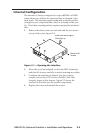
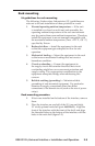
1. Locate DIP switch SW2 on the printed circuit board.
N
Use a Tweeker or other small screwdriver to toggle the
DIP switches between the on/closed or off/open positions.
2. For RGBHV, RGBS, or RGsB video, ensure that both
switches on the DIP switch block are off.
3. For RsGsBs video —
a. Ensure that both DIP switches are on.
b. Turn the rear panel SOG DIP switch on (up).
N
When both switches on the internal DIP switch SW2
are on, the rear panel SOG switch controls the output
format. When the SOG switch is on, the interface
outputs RsGsBs video; when the SOG switch is off, the
interface outputs RGBHV and RGBS video.
c. Horizontal sync —
For positive sync, ensure that a jumper is installed in
jumper block J9.
For negative sync, ensure that the jumper is removed
from jumper block J9.
d. Vertical sync —
For positive sync, ensure that a jumper is installed in
jumper block J20.
For negative sync, ensure that the jumper is removed
from jumper block J20.
Video clamping jumper
The interface is factory congured to clamp the sync timing to
the back porch. To clamp the sync timing to the tip of the sync
pulse, recongure the jumper as follows:
1. Locate J11 on the printed circuit board.
2. For sync timing clamped to the back porch, ensure that a
jumper is in place from pin 1 to pin 2.
3. For sync timing clamped to the sync tip, ensure that a
jumper is in place from pin 2 to pin 3.