


RGB 201 Rxi Universal Interface • Installation and Operation
Installation and Operation, cont’d
2-4
1
ON
2
J22
J23
RS-232
Connector
J11
1
2
3
1
1
1
SW2
Blue
Red
J28
J9 H Sync
J20 V Sync
J21 Enable
Sync
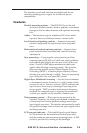
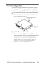
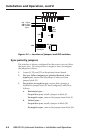
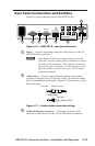
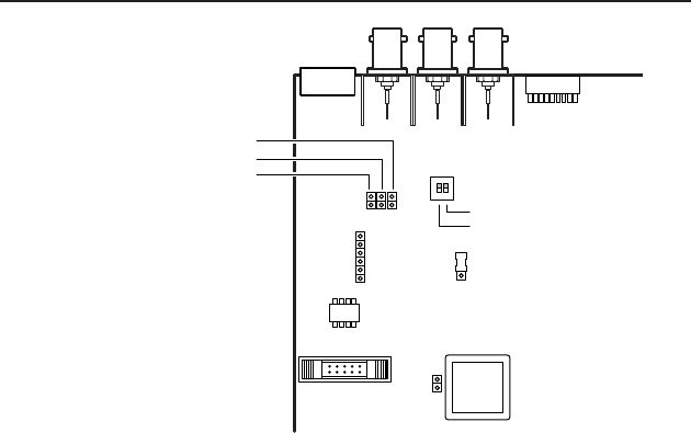
Figure 2-2 — Location of jumpers and DIP switches
Sync polarity jumpers
The interface is factory congured for the output sync to follow
the input sync. To force positive or negative sync, recongure
the jumper as follows:
1. Locate J9, J20, and J21 on the printed circuit board.
2. For sync follow (output sync polarity identical to the
input sync), ensure that the jumper is removed from
jumper block J21.
3. For positive or negative sync, ensure that a jumper is
installed in jumper block J21 and congure J9 and J20 as
follows:
a. Horizontal sync —
For positive sync, install a jumper in block J9.
For negative sync, remove the jumper from block J9.
b. Vertical sync —
For positive sync, install a jumper in block J20.
For negative sync, remove the jumper from block J20.