


Installation and Operation, cont’d
DVS 304 • Installation and Operation
2-26
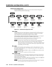
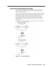
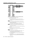
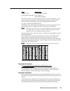
Input 1
Input 6
Input 5
Input 4
Input 3
Input 2
Input 64
Output 1 Input 4
Output 6 Input 4
Output 5
Output 4
Output 3
Output 2 Input 4
DVS 304 #1
DVS 304 #6
(optional)
DVS 304 #2
(optional)
Output to display
Output to display
Output to display
Output 4
Output 3
Matrix
Switcher
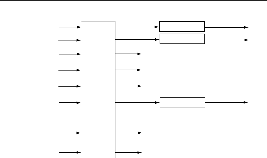
Figure 2-24 — Multiple DVS 304’s connected to a Matrix switcher
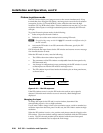
3. On the DVS 304, configure the input as follows:
a). Switch to input 4 on the DVS.
b). Set the following input sampling settings as desired: signal type,
horizontal and vertical start, pixel phase, total pixels, active pixels, and
active lines
N
Do not use auto detect setting for the input type when using input presets.
c). Set the following picture controls as desired: size, position, color, tint,
brightness, contrast, and detail.
d). Save the adjusted settings as input preset 1. Refer to chapter 3, “Serial
Communication”, for the SIS commands to save the preset.
N
Each input preset must be saved with the same number as the input on the
matrix switcher. For Example, input 24 on the matrix will be associated with
the input preset 24 on the DVS.
e). Repeat steps 2 and 3 for each input on the matrix that is to be used on the
DVS 304.
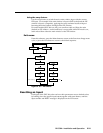
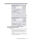
4. Synchronize the DVS to the matrix switcher as follows:
a). Open the Signal Enhancements Windows Control Program and connect
to the DVS 304.
N
Connection must be via IP (not RS-232).
b). From the Tools menu, select Sync DVS304 to Matrix Switcher... . The
Sync DVS304 to Matrix Switcher window opens.
c). In the IP Address field, enter the matrix switcher’s IP address.
d). Click Connect to Matrix button. The matrix switcher’s size is displayed
below the button.
e). From the drop-down menu next to Matrix Output feeding DVS 304
Input 4: select the matrix output number that is connected to Input 4 on
the DVS 304.