


2-7
DVS 304 • Installation and Operation
g
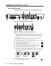
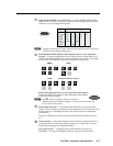
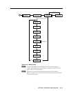
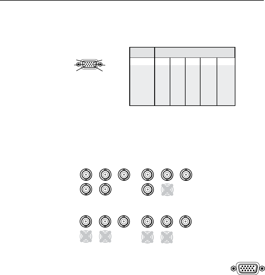
Video input 4: RGB/R-Y, Y, B-Y/YC/VID — Connect RGBHV, RGBS, RGsB,
RGBcvS, YUVi, YUVp, S-video and composite video through this 15-pin HD
connector. See pin configurations below.
Signal Input 4 Pin Configuraton
Pin 1 Pin 2 Pin 3 Pin 13 Pin 14
RGBHV R G B H V
RGBS R G B S
RGsB R G B
YUV R-Y Y B-Y
S-video Y C
Video Vid
RGB/R-Y,Y,B-Y/YC/VID
4
1
5
6
11
10
15
N
Equipment following the SCART interconnection standard may be connected to
the RGBcvS input cabling configuration.
h
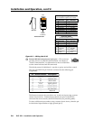
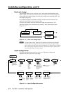
RGB (RGBHV, RGBS, RGsB) or HD component (R-Y, Y, B-Y) video BNC
outputs — Connect coaxial cables from a display device to these BNCs for a
scaled or pass-through RGB or a scaled component video output. The output
can be scaled to 62 different output rates (see table on page 2-15).
RGBHV
H/
HV
R
/R-Y
V
G
/Y
B
/B-Y
R
/R-Y
G
/Y
B
/B-Y
RGsB
H/
HV
V
R
/R-Y
V
G
/Y
R
G
B
S
H/
HV
B
/B-Y
B
/B-Y
Component Video (Y, R-Y, B-Y)
R
/R-Y
G
/Y
H/
HV
V
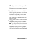
RGB or HD component (R-Y, Y, B-Y) 15-pin HD video output —
Connect an RGB video display or HD component video display
to this HD 15-pin connector.
N
Both
h
outputs are buffered and can be connected
simultaneously to two different displays. The sync and video formats will
be the same for both outputs.
i
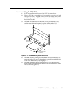
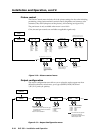
Reset button and LED — A recessed button that allows for manual resets
using an Extron Tweeker, pointed stylus or ballpoint pen. The unit can be reset
to four modes (see “Resetting the Unit” later in this chapter for additional
information).
The green LED flashes to show the reset mode indicators and that power is
on.
j
LAN connector — Plug an RJ-45 jack into this socket to connect the unit to a
computer network. Use a patch cable to connect to a switch, hub, or router.
See the following page for wiring information.
LAN Activity LED — A blinking yellow LED indicates LAN activity.
Link LED — The green LED lights to indicate a good LAN connection.
RGB/ R-Y ,Y,B -Y/ YC/ VID
4