Page 16
Page 17
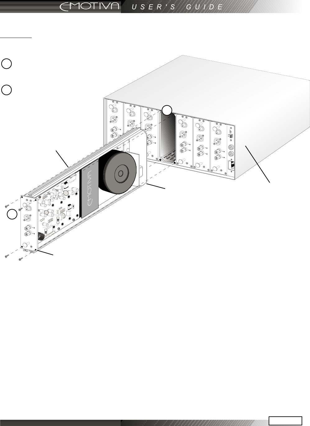
Inserting the EPM-300 Module
CAUTION: Make sure the MPS-1 chassis is NOT CONNECTED to line voltage during the installation
of the power modules!
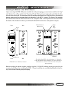
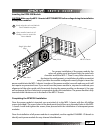
For proper installation of the power module, the
nylon rail guides must be aligned with the metal rails
channels inside the MPS-1. There is very little tolerance in
the design for misalignment, so installation should be somewhat
easy if you have the module congured correctly. Begin to insert the
power module into the MPS-1 chassis. Insertion of the power module is smooth and easy and it will
not require any excessive force. If you must force the power module in, stop and re-evaluate your
alignment of the nylon guide rails. Excessively forcing the power module can damage it. Use care
not to damage the fan or electronic components during this installation. The power module is fully
inserted when it bottoms out in the back of the MPS-1 chassis.
Completing the EPM-300 Installation
Once the power module is inserted, you must attach it to the MPS-1 chassis with four #2 phillips
screws (provided). The screw holes on the back panel should line up to threaded holes in the MPS-
1 chassis. Install and tighten the screws, then proceed with the installation of subsequent power
modules.
Once the installation of all power modules is completed, use the supplied CHANNEL I.D. decals to
identify each power module for easy channel identication.
Front
Back
Single Nylon Rail
(Top)
Gently align the rails and slide the
Power Module into place
MPS-1 Chassis
Once installed, attach (4) #2
Phillips screws to secure the
Power Module
2
1
2
1


