


Page 14
Page 15
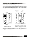
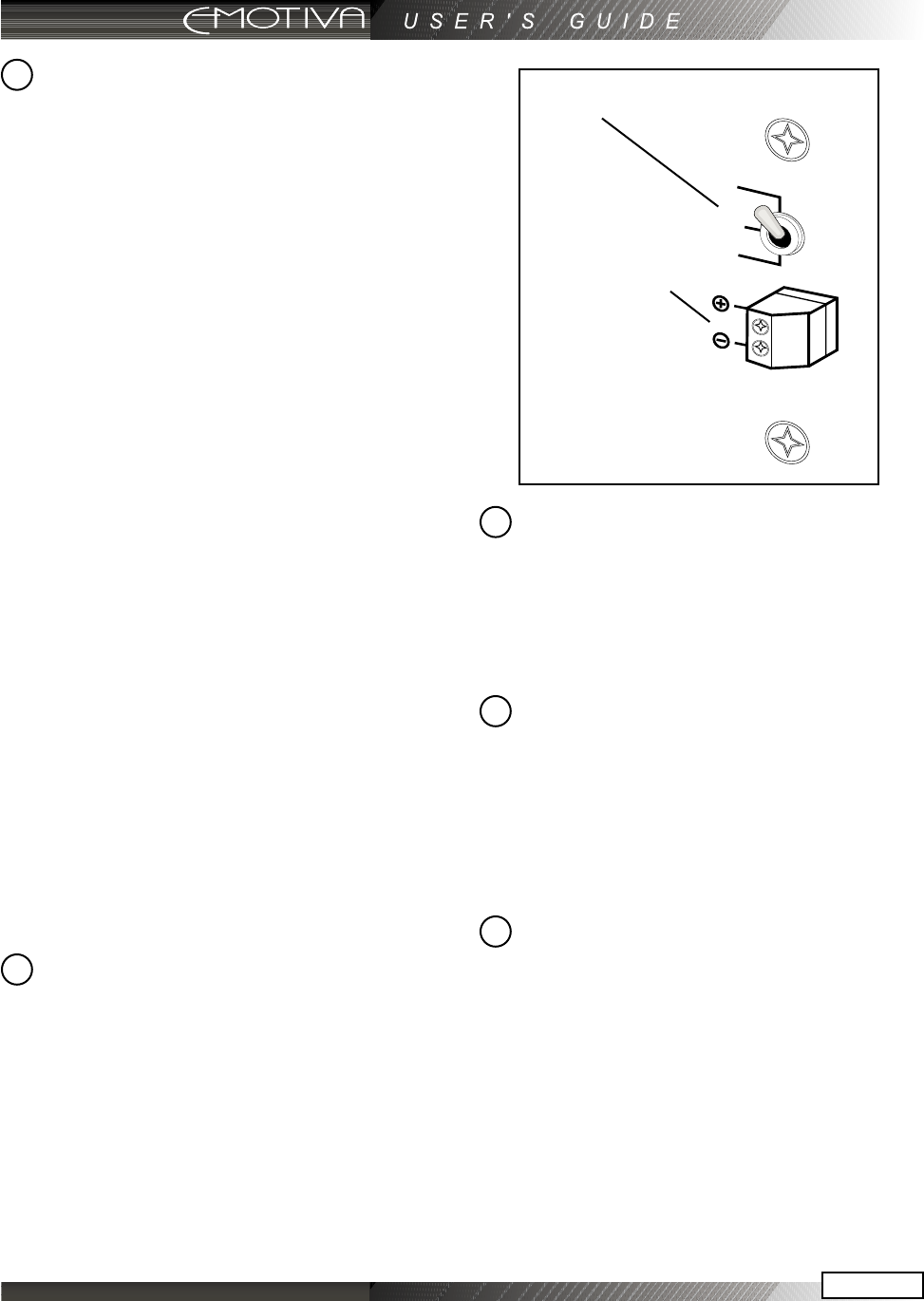
Turn On Selector Switch
This switch allows you to select how the
amplier will turn on and o.
In the ON (Up) position, the switch on the
front of the amplier is the method you
will use to power up and power down the
amplier. Please note that in this congu-
ration, you must manually power up and
power down the amplier each time you
use it or it will have unnecessary standby
current draw.
In the SIGNAL (Middle) position, the am-
plier automatically turns on whenever it
senses an audio signal on any one of the
seven amplier channels. The circuit stays
active for a full minute after the absence of
any audio signal to account for quiet pas-
sages of music or dialogue.
In the TRIGGER (Down) position, the ampli-
er’s ON and OFF functions are controlled
by a trigger from a source or preamplier
device. The trigger accepts 12 VDC and will
turn the amplier on whenever a trigger is
present (See #5). When there is no trigger,
the amplier goes into standby mode. This
is the preferred method for activating the
MPS-1.
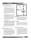
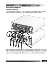
External Trigger Connection
This external trigger connection allows
the amplier to be turned ON and OFF by
a control device such as a source unit or
preamplier. It can also be used with most
home automation controllers. The trigger
requires a 12 VDC trigger. This is the pre-
ferred method of activating the MPS-1. See
page 23 for connection details.
Fuse #1
This fuse is for the power supply of the MPS-
1 chassis. It is a TL15AL type rated a 15A, 250
V. If the fuse ever fails, be sure to replace it
with the same type and rated fuse.
Fuse #2
This fuse is also for the power supply of
the MPS-1 chassis. It is a TL15AL type rated
a 15A, 250 V. If the fuse ever fails, be sure
to replace it with the same type and rated
fuse.
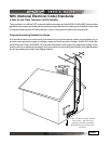
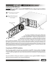
IEC Line Cord Socket
The MPS-1 comes with a detachable line
cord which connects here. Plug the line
cord into an AC wall socket which is cor-
rectly configured with the voltage and
current supply specied for the MPS-1. Do
not plug this line cord into a power strip,
it must plug directly into a wall socket. For
more details on AC power considerations,
see page 19.
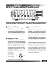
Turn On Selector Switch
External Trigger
Connection
5
6
7
4
8