


Page 12
Page 13
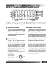
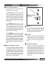
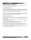
Unbalanced RCA Inputs
The MPS-1 has one unbalanced RCA input
available for each amplier channel mod-
ule. Connect this to the corresponding RCA
jack on your preamplier to provide signal
to the amplier channel. See page 21 for a
connection diagram.
Speaker Output Terminals
The speaker output terminals for each am-
plier channel are located just below the
balanced XLR input jack. The top post of
each binding post pair is the positive out-
put, and connects to the positive (red) post
of your speaker. The bottom post of each
pair is the negative, and connects to the
negative (black) post of your speaker. The
posts can accept bare wire, spade terminals,
and dual or single banana connectors.
Spade connections or banana plugs ensure
a simple, solid t in the terminal whereas
bare wire may be awkward when the ter-
minal is screwed down to compress the
wire into place. Keep in mind that if you
use “dual banana” plugs and “stack” them,
you will be creating a parallel connection.
For more details on series and parallel con-
nections, see pages 24-25.
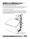
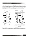
MPS-1 Finished Rear Panel Layout
Balanced XLR Inputs
The MPS-1 has one balanced XLR input
available for each amplier channel mod-
ule. Connect this to the corresponding
XLR jack on your preamplier to provide
signal to the amplier channel. If you have
a choice, use the balanced XLR connections
whenever possible. Balanced connections
oer superior noise immunity over unbal-
anced RCA connections.
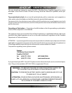
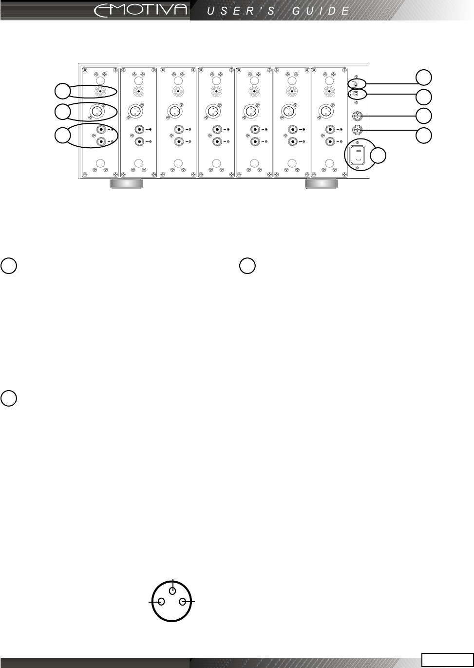
On the balanced XLR connector, the wiring
is as follows:
Pin #1 = Ground
Pin #2 = Signal +
Pin #3 = Signal -
See page 22 for a connection diagram.
Pin #1
Pin #2
Pin #3
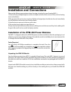
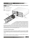
Note: Before connecting any components to the MPS-1, the individual power modules must rst be
installed into the chassis. Please see pages 15-17 for details on the power module installation.
5
6
7
1
2
3
4
8
1
2
3