


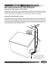
Page 16
Page 17
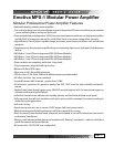
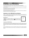
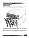
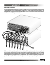
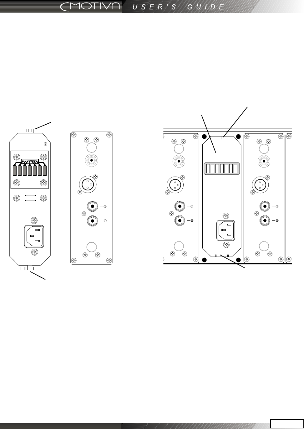
Orienting the Module to the MPS-1 Chassis
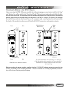
Upon removing the EPM-300 power module from the packaging, you must orient which is the “top”
and “bottom” as well as which is the “front” and “back”. The top has a single nylon rail while the bot-
tom has two nylon rails. It is important that the module be placed in so that the rails on the top and
bottom align with the corresponding “rail channels” in the MPS-1 chassis. The front of the module
that will be inserted into the chassis has an AC receptacle and a small printed circuit board while
the back of the module is where you will nd the RCA/XLR connectors and speaker outputs.
Before inserting the power module, conrm that the 115/230 VAC voltage setting is correct for the
country in which you are installing the MPS-1. These should be set correctly (by default) at the fac-
tory at the time of testing and packaging.
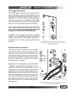
Front Back
Single
Rail
(Top)
Dual
Rails
(Bottom)
EPM-300 Power Module orientation
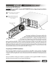
The back of the MPS-1 chassis looking “in” where the
EPM-300 module will be installed. (For clarity, the EPM-
300 modules are shown installed on either side of the
empty opening)
EPM-300 Power
Module bay
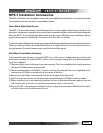
Single
Rail
(Top)
Dual Rails
(Bottom)
Front Back