


ENGLISH
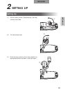
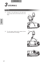
SETTING UP
76
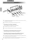
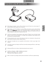
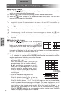
r Connecting to the unit having the analog RGB output terminal
Connect the analog RGB cable to the [RGB IN] terminal on the rear panel.
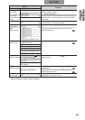
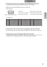
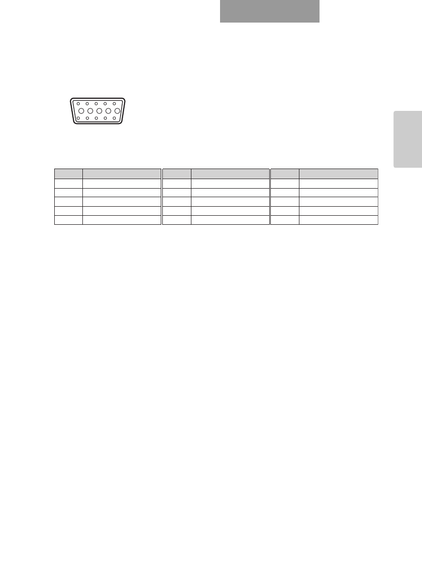
• Specifications of the analog RGB input terminal of this product
Signal allocation
Pin assignment
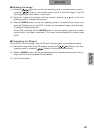
t Connecting to the unit having the composite vide input terminal
Connect the video cable with RCA pin plug to the [VIDEO OUT] terminal on the rear panel.
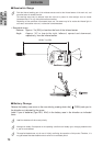
y Connecting to the unit having S-video input terminal
Connect the S-video cable to the [S-VIDEO OUT] terminal on the rear panel. If the unit to be
connected has a Y/C-separated connector, a conversion adapter is required.
109876
54321
15 14 13
DSUB 15P shrink terminal (Female)
12 11
Video signal : Analog 0.7V(p-p) 75Ω terminated
Horizontal synchronized signal : TTL level (Positive/negative polarity)
Vertical synchronized signal : TTL level (Positive/negative polarity)
Pin No. Name
1
Video signal (Red)
2
Video signal (Green)
3
Video signal (Blue)
4
N.C
5
GND
Pin No. Name
6
GND (Red)
7
GND (Green)
8
GND (Blue)
9
N.C
10
GND
Pin No. Name
11
GND
12
N.C
13
Horizontal synchronized signal
14
Vertical synchronized signal
15
N.C