


ENGLISH
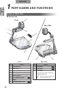
PART NAMES
AND
FUNCTIONS
65
q
w
e
r
t
u
y
i
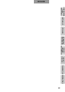
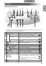
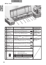
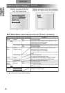
■ Rear Panel
Name Function
q DVI OUT To output digital video signal to the projector, the Camera image
(DVI Output Terminal)
PC monitor or other DVI input device SD mode
w RGB OUT To output analog video signal to the projector, the Camera image
(Analog RGB PC monitor or other RGB input device [RGB IN] image
Output Terminal) SD mode
e RGB IN Input image is output from the analog RGB output
(Analog RGB terminal when RGB IN ( ) is selected with image
Input Terminal) select button.
r VIDEO OUT To output image from the RCA pin-jack terminal to
Camera image
(Composite Video
the NTSC/PAL-system monitor (e.g., TV monitor) SD mode
Output Terminal)
t S-VIDEO OUT To output image from the Mini DIN 4P terminal to
(S-video Output the NTSC/PAL-system monitor (e.g., TV monitor)
Terminal)
y RS-232C To control the main unit from a PC through the
(RS-232C Terminal)
RS-232C cable
u 12VDC IN Socket for the AC adapter
(Power Socket)
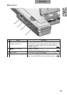
i (DIP Switch) To switch the following:
[A] key: Image output system
[B] key: Image output screen size
When switching the DIP switch key settings, be sure
to turn OFF the power supply to the main unit.
Image whose display
is selectable with
image select button
P.75
P.75
P.76
P.76
P.76
P.96
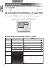
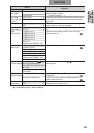
0
1
[A] key
NTSC
PAL
[B] key
Over-scan
Under-scan
0
1
A B
Display of Rear Panel