


CyberData Corporation 930095K Operations Guide
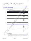
Mount the Speaker
26
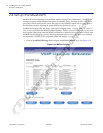
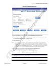
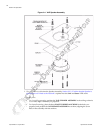
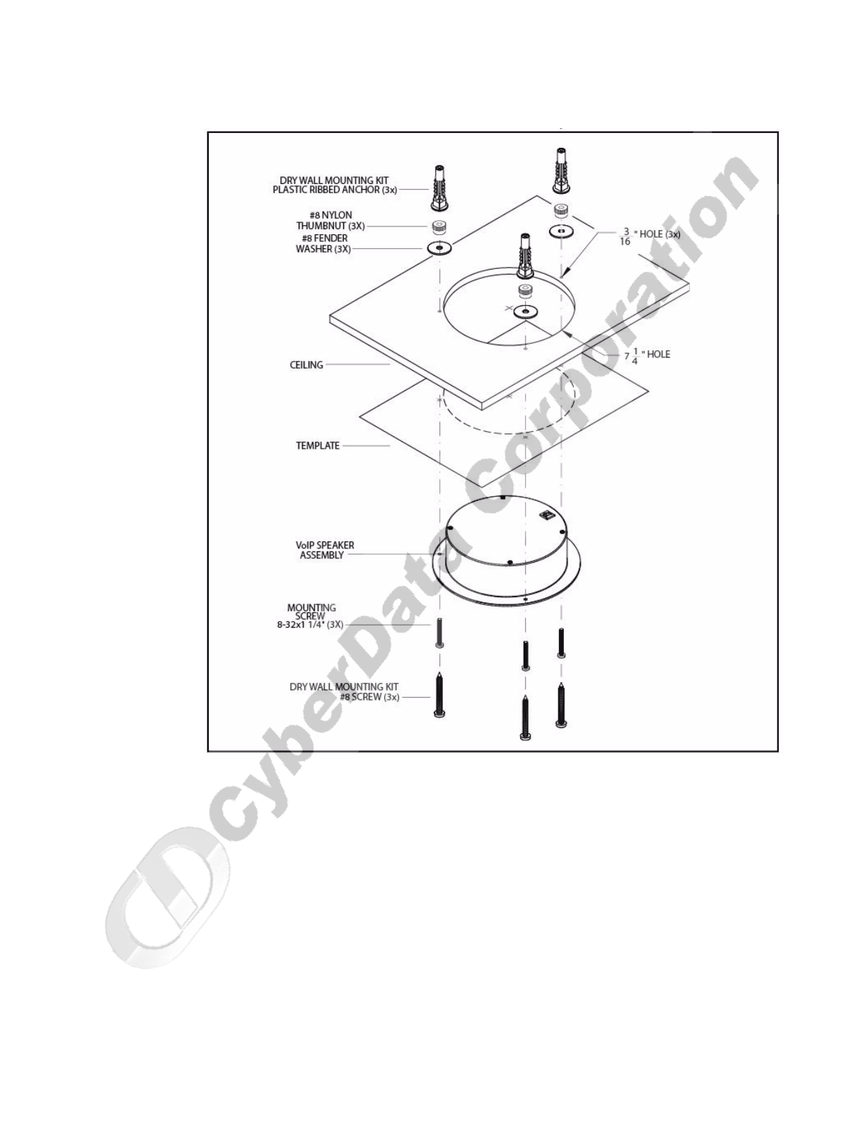
Figure A-1. VoIP Speaker Assembly
2. Plug the Ethernet cable into the Speaker Assembly. Section 2.2.2, "Confirm that the Speaker is
Operational and Linked to the Network" explains how the Lin
k and Status LEDs work.
3. At this point:
•For dr
op ceiling mounting, position the VoIP SPEAKER ASSEMBLY in the ceiling so that its
screw holes align with those you prepared.
•For drywall mou
nting, place the three PLASTIC RIBBED ANCHORS in the holes you
prepared, and position the VoIP SPEAKER ASSEMBLY over them, aligning the screw
holes in the assembly with the anchors.