


page 41
CTs Power Amplifi ers
Operation Manual
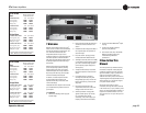
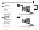
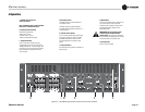
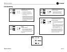
4.3 Back Panel Controls
and Connectors
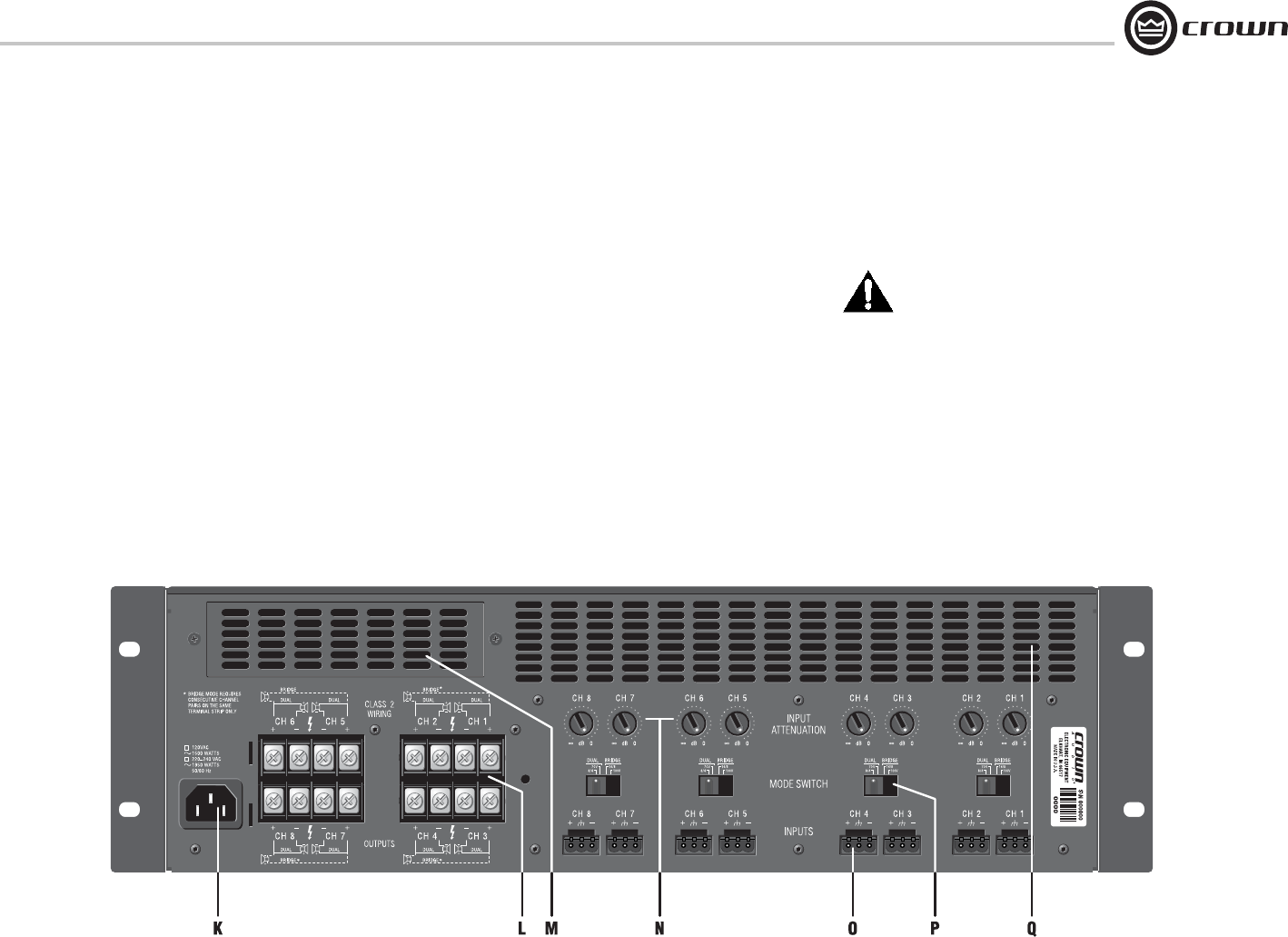
Note: CTs 8200 is shown. Some CTs 4200
features are in different locations.
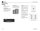
K. AC Power Cord Connector
Standard IEC type 320 inlet.
120V models: 15-amp.
220-240V models: 10-amp.
Voltage is indicated above IEC inlet.
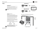
L. Output Connectors
One four-pole terminal strip for every two
chan nels with touch-proof cover. Accepts up to
10 AWG terminal forks. To connect outputs, fi rst
remove the touch-proof cover plate covering the
terminal strip by removing the screw which
holds it in place.
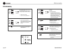
M. Accessory Panel
CTs 4200: Accepts an optional IQ-MC4A or
VCA-MC4A module.
CTs 8200: Accepts an optional IQ-MC8 or
VCA-MC8 module (explained in Section 5.3.1,
Control Modules).
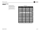
N. Channel Level Controls
One 21-position detented rotary potentiometer
per channel, ranging from infi nity (-70 dB) to
0 dB attenuation. Refer to Section 5.2.4 for
pre cise dB attenuation increments for each
detent.
O. Input Connectors
Removable Phoenix-style barrier connectors for
balanced input.
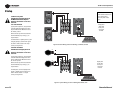
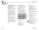
P. Mode Switch
Used on each consecutive pair of channels, this
four-position switch is used to select the
ampli fi er’s mode of operation: Dual 8/4 ohms,
Dual 70V, Bridge-Mono 16/8 ohms, and
Bridge-Mono 100V.
IMPORTANT: Be sure to power off the
amplifi er before change the Mode-
switch setting. If this is not done, the Bridge
light will fl ash to indicate that the power must be
cycled off and back on to reset the mode.
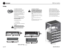
Q. Cooling Vents
Front-to-rear forced airfl ow.
4 Operation
Figure 4.2 CTs 8200 back panel (shown with touch-proof cover removed).