


page 13
CTs Power Amplifi ers
Operation Manual
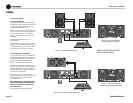
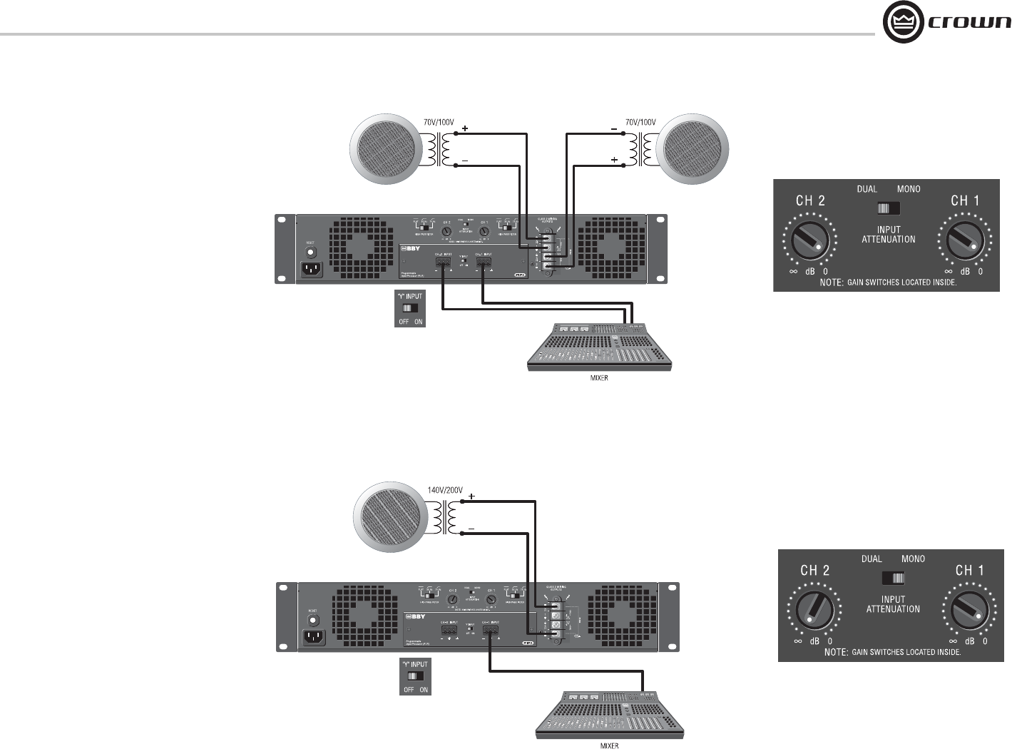
3.6.3 Dual 70V/100V Mode
Typical input and output wiring, along with
Atten uator and Mode Switch settings are shown in
Fig ures 3.10 and 3.11. Make sure the Mode
switch is set to the “Dual” position when operating
in Dual mode.
INPUTS: Connect input wiring to both channels.
OUTPUTS: In Dual Mode, the CTs 600/1200 can
power 25/50/70V lines; the CTs 2000/3000 can
power 25/50/70/100V lines. Connect each
chan nel of output connectors to speakers that
have the appropriate transformers.
.
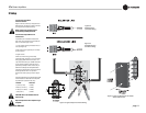
3.6.4 Bridge-Mono 140V/200V Mode
Typical input and output wiring, along with
Atten uator and Mode Switch settings are shown in
Fig ures 3.12 and 3.13. Make sure the Mode
switch is set to the “Mono” position when
operating in Bridge-Mono mode.
INPUTS: Connect input wiring to Channel 1 only.
OUTPUTS: In Bridge-Mono mode, the CTs
600/1200 can power 140V lines; the CTs
2000/3000 can power 140V and 200V lines.
Connect speak ers with 140V or 200V
transformers across the positive terminals of the
channel pair. Do not use the negative terminals of
the channel pair when the pair is being operated in
Bridge-Mono mode. Refer to Section 3.5 for
output connector pin assignments.
NOTE: When operating in Bridge-Mono
mode, turn down (full CCW) the Input
Attenuator for Channel 2. The Channel-1
Input Attenuator works both channels.
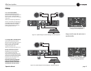
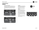
Figure 3.11 System Wiring and Y-Switch Setting for 70V/100V Operation
Figure 3.12 Attenuator and Mode-Switch
Settings for 70V/100V Operation
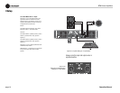
Figure 3.13 System Wiring and Y-Switch Setting for 140V/200V Operation
Figure 3.14 Attenuator and Mode-Switch
Settings for 140V/200V Operation
3 Setup
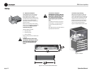
Always route the input and output wires in
separate bundles.