


page 11
CTs Power Amplifi ers
Operation Manual
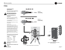
3.4 Choose Input Wire
and Connectors
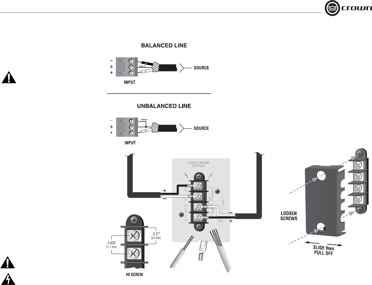
Figure 3.3 shows connector pin assignments for
balanced wiring, and Figure 3.4 shows connec tor
pin assignments for unbalanced wiring.
NOTE: Custom wiring should only be
per formed by qualifi ed personnel.
3.5 Choose Output Wire and
Con nectors
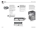
A protective cover is installed over the barrier-
strip output. Some models have a cover with two
holes. To remove this type of cover:
1. Loosen screws inside top and bottom holes of
cover (see Figure 3.6).
2. Slide cover to left or right, then pull it off away
from the amplifi er.
3. Tighten screws.
Crown recommends using professionally
con structed, high-quality, two- or four-conductor,
heavy gauge speaker wire and connectors. You
may use terminal forks up to 10 AWG or bare wire
for your output connectors (see Figure 3.5). To
prevent the possibility of short-circuits, wrap or
otherwise insulate exposed loudspeaker cable
connectors. For best results, Crown recom mends
Panduit part #PV10-10LF-L or equivalent
terminal fork. Screw spacing is shown in Figure
3.5.
Using the guidelines below, select the appropri ate
size of wire based on the distance from amplifi er
to speaker (low-impedance loads only).
Distance Wire Size
up to 25 ft. (7.6m) 16 AWG
26-40 ft. (7.9-12.2m) 14 AWG
41-60 ft. (12.5-18.3m) 12 AWG
> 60 ft (18.3m) 10 AWG
CAUTION: Never use shielded cable for
output wiring.
Replace output cover after output wiring is
complete.
Figure 3.5 Typical Output Connector Wiring
3 Setup
Figure 3.3
Balanced Input
Connector Wiring
Figure 3.4
Unbalanced Input
Connector Wiring
Figure 3.6 How to Remove the Two-Holed
Barrier-Block Cover