


Operation Manual
CTs Power Amplifi ers
page 36
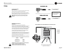
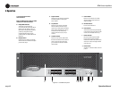
3.6 Wire Your System
CAUTION: Never change the position of
the Mode Switch while the amplifi er
power is on. See Section 5.2.2 for more
information.
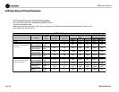
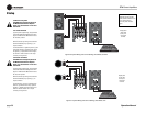
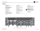
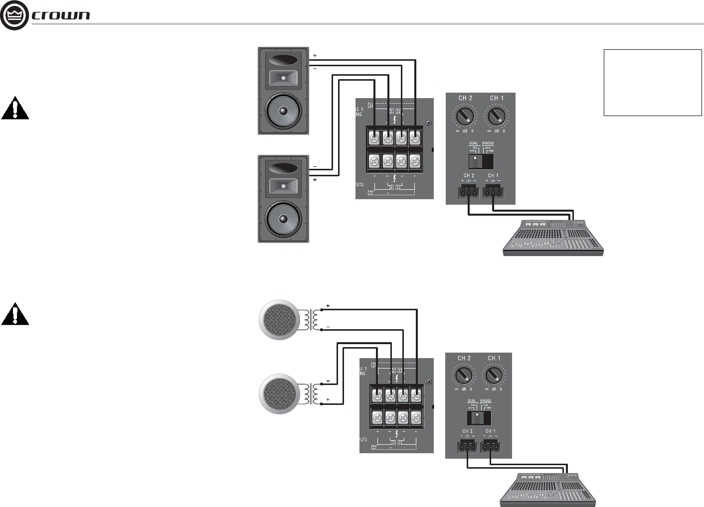
3.6.1 Dual 8/4 Mode
Typical input and output wiring, along with level
control and Mode Switch settings are shown in
Figure 3.6. Make sure the Mode switch is set to
the “Dual 8/4” position.
INPUTS: Connect input wiring for each channel.
OUTPUTS: Maintain proper polarity (+/–) on
output connectors.
Connect the Channel 1 speaker’s positive (+) lead
to amplifi er Channel 1 positive terminal; repeat
for negative (–). Repeat each channel wir ing as
for Channel 1. Refer to Section 3.5 for output
connector pin assignments.
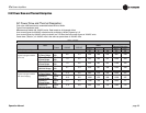
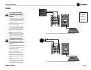
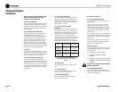
3.6.2 Dual 70V Mode
CAUTION: Never change the position of
the Mode Switch while the amplifi er
power is on. See Section 5.2.2 for more
information.
Typical input and output wiring, along with level
control and Mode Switch settings are shown in
Figure 3.7. Make sure the Mode switch is set to
the “Dual 70V” position.
INPUTS: Connect input wiring for each channel.
OUTPUTS: Maintain proper polarity (+/–) on
output connectors.
Connect Channel 1 positive (+) speaker load to
Channel 1 positive terminal of amp; repeat for
negative (–). Repeat each channel wiring as for
Channel 1. Refer to Section 3.5 for output
con nector pin assignments.
3 Setup
Figure 3.6 System Wiring and Control Settings, Dual Mode, 8/4 Ohm
Figure 3.7 System Wiring and Control Settings, Dual Mode, 70V.
Output panel
shown with
touch-proof
cover plate
removed.
Output panel
shown with
touch-proof
cover plate
removed.
CH 4
DUAL DUAL
BRIDGE
CH 3
CH 2
DUAL DUAL
BRIDGE
CH 1
See the Crown Amplifi er
Appli cation Guide, available
online at www.crownaudio.com,
for pin assignments for
commonly used connector
types.
CH 4
DUAL DUAL
BRIDGE
CH 3
CH 2
DUAL DUAL
BRIDGE
CH 1
70V
70V