


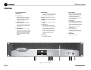
Operation Manual
CTs Power Amplifi ers
page 12
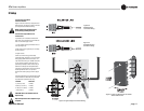
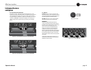
3.6 Wire Your System
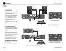
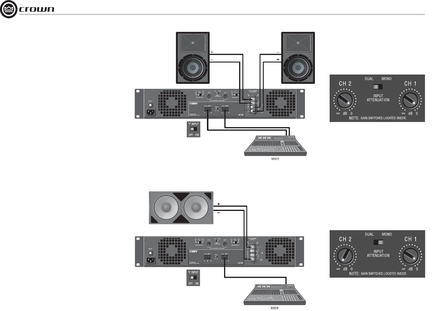
3.6.1 Dual 8/4/2 Mode
Typical input and output wiring, along with Attenuator
and Mode Switch settings are shown in Figures 3.6 and
3.7. Make sure the Mode switch is set to the “Dual”
posi tion when operating in Dual mode.
INPUTS: Connect input wiring for each channel. The Y
switch on the rear PIP panel can be used to parallel the
channel inputs when only mono input signals are
neces sary. The amplifi er’s channel outputs are still
indepen dent.
OUTPUTS: Maintain proper polarity (+/–) on
output connectors.
Connect the Channel 1 speaker’s positive (+) lead to
amplifi er Channel 1 positive terminal; repeat for negative
(–). Repeat Channel-2 wiring as for Channel 1. Refer to
Section 3.5 for output connector pin assignments.
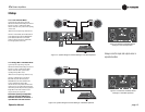
3.6.2 Bridge-Mono 16/8/4 Mode
Typical input and output wiring, along with Attenuator
and Mode Switch settings, are shown in Figures 3.8 and
3.9. Make sure the Mode switch is set to the “Mono”
position when operating in Bridge-Mono mode.
INPUTS: Connect input wiring to Channel 1 only.
OUTPUTS: Connect the speaker across the positive
ter minals of each channel pair. Do not use the negative
ter minals of the channel pair when the pair is being
operated in Bridge-Mono mode. Refer to Section 3.5 for
output connector pin assignments.
NOTE: Crown provides a reference of wiring pin
assign ments for commonly used connector types in the
Crown Amplifi er Application Guide available at
www.crownaudio.com.
NOTE: When operating in Bridge-Mono mode,
turn down (full CCW) the Input Attenuator for
Channel 2. The Channel-1 Input Atttenuator
works both channels.
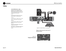
See the next page for constant-voltage operation.
Figure 3.7 System Wiring, Dual Mode.
Figure 3.8 Attenuator and Mode-
Switch Settings for Dual Mode
Figure 3.9 System Wiring, Bridge-Mono Mode
Figure 3.10 Attenuator and Mode-
Switch Settings for Bridge-Mono Mode
3 Setup
Always route the input and output
wires in separate bundles.